WIRING – MAIN POWER
These units are rated for 60/50 Hz operation as follows.
NOTE: This system must be controlled only by the Bard
| Volts | Operating | |
Electrical | Hz | Voltage | |
Code | Phase | Range | |
|
|
| |
197 - 253 | |||
180 - 242 | |||
| |||
|
|
| |
197 - 253 | |||
180 - 242 | |||
| |||
|
|
| |
414 - 506 | |||
360 - 440 | |||
| |||
|
|
|
Refer to the unit rating plate for wire sizing information and maximum fuse or “HACR” type circuit breaker size. Each outdoor unit is marked with a “Minimum Circuit Ampacity”. This means that the field wiring used must be sized to carry that amount of current. Depending on the installed KW of electric heat, there may be two field power circuits required. If this is the case, the unit serial plate will so indicate. All models are suitable only for connection with copper wire. Each unit and/or wiring diagram will be marked “Use Copper Conductors Only”. These instructions must be adhered to. Refer to the National Electrical Code (NEC) for complete current carrying capacity data on the various insulation grades of wiring material. All wiring must conform to NEC and all local codes.
The electrical data lists fuse and wire sizes (75° C copper) for all models including the most commonly used heater sizes. Also shown are the number of field power circuits required for the various models with heaters.
The unit rating plate lists a “Maximum Time Delay Relay Fuse” or “HACR” type circuit breaker that is to be used with the equipment. The correct size must be used for proper circuit protection and also to assure that there will be no nuisance tripping due to the momentary high starting current of the compressor motor.
The disconnect access door on this unit may be locked to prevent unauthorized access to the disconnect. To convert for the locking capability, bend the tab located in the bottom
See “Start Up” section for important information on three phase scroll compressor start ups.
See Table 3 for Electrical Specifications.
WIRING – LOW VOLTAGE WIRING
230/208V, 1 phase and 3 phase equipment dual primary voltage transformers. All equipment leaves the factory wired on 240V tap. For 208V operation, reconnect from
240V to 208V tap. The acceptable operating voltage range for the 240 and 208V taps are:
TAP | RANGE |
240 | 253 – 216 |
208 | 220 – 187 |
NOTE: The voltage should be measured at the field power connection point in the unit and while the unit is operating at full load (maximum amperage operating condition).
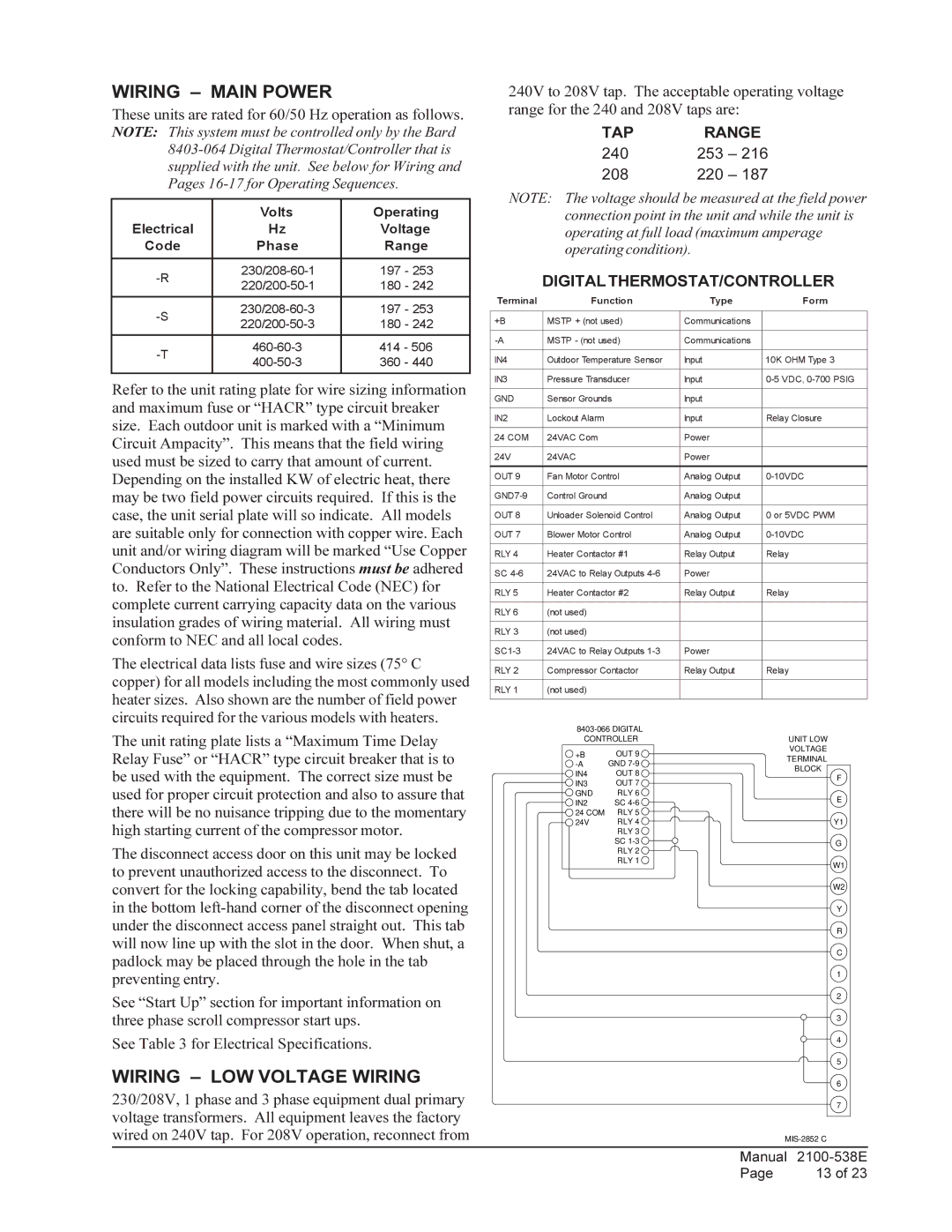
DIGITAL THERMOSTAT/CONTROLLER
Terminal | Function | Type | Form |
|
|
|
|
+B | MSTP + (not used) | Communications |
|
|
|
|
|
MSTP - (not used) | Communications |
| |
|
|
|
|
IN4 | Outdoor Temperature Sensor | Input | 10K OHM Type 3 |
|
|
|
|
IN3 | Pressure Transducer | Input | |
|
|
|
|
GND | Sensor Grounds | Input |
|
|
|
|
|
IN2 | Lockout Alarm | Input | Relay Closure |
|
|
|
|
24 COM | 24VAC Com | Power |
|
|
|
|
|
24V | 24VAC | Power |
|
|
|
|
|
OUT 9 | Fan Motor Control | Analog Output | |
|
|
|
|
Control Ground | Analog Output |
| |
|
|
|
|
OUT 8 | Unloader Solenoid Control | Analog Output | 0 or 5VDC PWM |
|
|
|
|
OUT 7 | Blower Motor Control | Analog Output | |
|
|
|
|
RLY 4 | Heater Contactor #1 | Relay Output | Relay |
|
|
|
|
SC | 24VAC to Relay Outputs | Power |
|
|
|
|
|
RLY 5 | Heater Contactor #2 | Relay Output | Relay |
|
|
|
|
RLY 6 | (not used) |
|
|
|
|
|
|
RLY 3 | (not used) |
|
|
|
|
|
|
24VAC to Relay Outputs | Power |
| |
|
|
|
|
RLY 2 | Compressor Contactor | Relay Output | Relay |
|
|
|
|
RLY 1 | (not used) |
|
|
|
|
|
|
| |||
CONTROLLER | UNIT LOW | ||
+B | OUT 9 | VOLTAGE | |
TERMINAL | |||
GND | |||
BLOCK | |||
IN4 | OUT 8 | ||
F | |||
IN3 | OUT 7 | ||
| |||
GND | RLY 6 | E | |
IN2 | SC | ||
| |||
24 COM | RLY 5 |
| |
24V | RLY 4 | Y1 | |
RLY 3 |
| |
SC | G | |
RLY 2 | ||
| ||
RLY 1 | W1 | |
| ||
| W2 | |
| Y | |
| R | |
| C | |
| 1 | |
| 2 | |
| 3 | |
| 4 | |
| 5 | |
| 6 | |
| 7 | |
|
Manual | |
Page | 13 of 23 |