
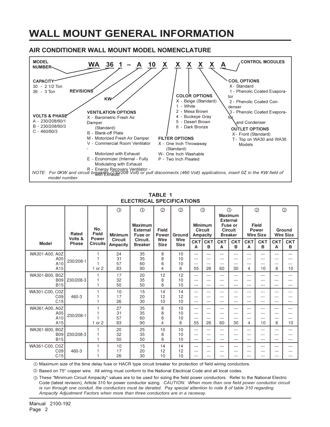
WA301, WA361 specifications
The Bard WA361 and WA301 are two advanced wall-mounted air conditioning systems designed for commercial and residential use. These units are engineered to provide efficient cooling and heating while optimizing energy consumption.One of the standout features of the Bard WA361 and WA301 models is their compact design. This allows for easy installation in various spaces where traditional floor-mounted units may not fit. Ideal for areas such as classrooms, offices, or small retail locations, these units can be mounted high on the wall, freeing up valuable floor space.
Both models leverage Bard’s advanced heat pump technology. This technology allows for reverse-cycle functionality, meaning they can provide both cooling in summer and heating in winter. The WA361 model offers a heating capacity of up to 36,000 BTUs while the WA301 provides a slightly lower capacity of 30,000 BTUs, making them suitable for different size requirements.
Energy efficiency is prioritized in these models. They come equipped with high Seasonal Energy Efficiency Ratings (SEER), which ensures lower electric bills and reduced environmental impact. Additionally, the units have been designed to operate quietly, maximizing comfort without the disruptive noise often associated with HVAC systems.
Another notable characteristic is the advanced control system. The Bard WA361 and WA301 feature programmable thermostats that allow users to set specific comfort levels according to their schedules. This not only enhances user control but also boosts energy-saving potential.
Moreover, both models are built with durable materials to ensure longevity and reliability. Their internal components are engineered to withstand harsh conditions, making them a preferred choice for various settings, including industrial environments.
Bard emphasizes ease of maintenance in the design of these units. The filters are easily accessible and can be replaced or cleaned with minimal effort. This feature significantly extends the lifespan of the unit and ensures that it operates at peak performance.
In summary, the Bard WA361 and WA301 air conditioning units represent a blend of innovative technology and practical design. Their energy-efficient operation, compact installation capability, and advanced heating and cooling functions make them exemplary solutions for those seeking reliable comfort control in diverse applications. Whether for small businesses or residential spaces, these units aim to deliver exceptional performance with a focus on sustainability and efficiency.