FRONT PANEL CONTROLS | REAR PANEL CONNECTIONS | ||||||||||||
|
|
|
|
|
|
|
|
|
|
|
|
|
|
|
|
|
|
|
|
|
|
|
|
|
|
|
|
|
|
|
|
|
|
|
|
|
|
|
|
|
|
|
|
|
|
|
|
|
|
|
|
|
|
|
|
|
|
|
|
|
|
|
|
|
|
|
|
|
|
1 | 2 | 3 | 4 | 5 | 6 |
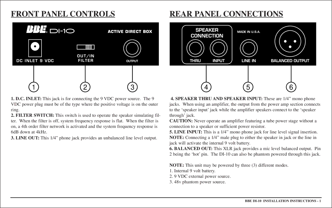
1.D.C. INLET: This jack is for connecting the 9 VDC power source. The 9 VDC power plug must be of the type where the positive voltage is on the outer ring.
2.FILTER SWITCH: This switch is used to operate the speaker simulating fil- ter. When the filter is off, system frequency response is flat. When the filter is on, a 4th order filter network is activated and the system frequency response is 6dB down at 4kHz.
3.LINE OUT: This 1/4” phone jack provides an unbalanced line level output.
4.SPEAKER THRU AND SPEAKER INPUT: These are 1/4” mono phone
jacks. When using an amplifier, the output from the power amp section connects to the ‘speaker input’ jack while the amplifier speakers connect to the ‘speaker through’ jack.
CAUTION: Never operate an amplifier featuring a tube power stage without a connection to a speaker or sufficient power resistor.
5.LINE INPUT: This is a 1/4” mono phone jack for line level signal insertion. NOTE: Connecting a 1/4” male plug to either the speaker in jack or the line in jack will activate the internal 9 volt battery.
6.BALANCED OUT: This XLR jack provides a mic level balanced output. Pin
2being the ‘hot’ pin. The
NOTE: This unit may be powered by three (3) different modes.
1.Internal 9 volt battery.
2.9 VDC external power source.
3.48v phantom power source.
BBE
