“The Peak Of Detection”
| MATRIX |
FCC ID#: | USER’S GUIDE |
| DIGITAL INDUCTIVE LOOP SENSORS |
1 Description
The MATRIX (10MATRIX) Digital Inductive Loop Detector is the ideal solution for parking barrier control, motorized gates and doors, vehicle access control and industrial control systems. The MATRIX is a high performance single or
10MATRIXS110 : Single loop detector with 110 to 120 V AC power supply.
10MATRIXS220 : Single loop detector with 220 to 240 V AC power supply.
10MATRIXS1224 : Single loop detector with 12 to 24 V AC/DC power supply.
10MATRIXD110 : Dual loop detector with 110 to 120 V AC power supply.
10MATRIXD220 : Dual loop detector with 220 to 240 V AC power supply.
10MATRIXD1224 : Dual loop detector with 12 to 24 V AC/DC power supply.
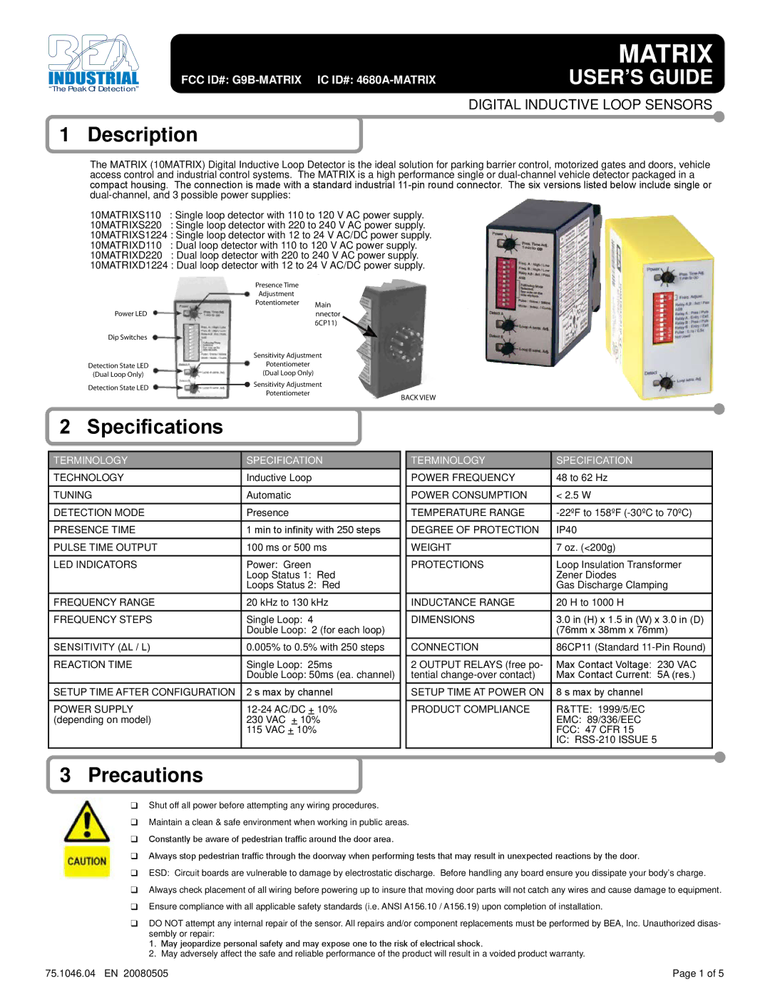
Presence Time
Adjustment
Potentiometer Main
Power LEDConnector (86CP11)
Dip Switches
|
| Sensitivity Adjustment |
|
Detection State LED |
| Potentiometer |
|
(Dual Loop Only) |
| (Dual Loop Only) |
|
Detection State LED |
| Sensitivity Adjustment |
|
|
| ||
| Potentiometer |
| |
|
| BACK VIEW | |
|
|
|
2 Specifications
TERMINOLOGY | SPECIFICATION |
TECHNOLOGY | Inductive Loop |
TUNING | Automatic |
DETECTION MODE | Presence |
PRESENCE TIME | 1 min to infinity with 250 steps |
PULSE TIME OUTPUT | 100 ms or 500 ms |
LED INDICATORS | Power: Green |
| Loop Status 1: Red |
| Loops Status 2: Red |
FREQUENCY RANGE | 20 kHz to 130 kHz |
FREQUENCY STEPS | Single Loop: 4 |
| Double Loop: 2 (for each loop) |
SENSITIVITY (ΔL / L) | 0.005% to 0.5% with 250 steps |
REACTION TIME | Single Loop: 25ms |
| Double Loop: 50ms (ea. channel) |
SETUP TIME AFTER CONFIGURATION | 2 s max by channel |
POWER SUPPLY | |
(depending on model) | 230 VAC + 10% |
| 115 VAC + 10% |
|
|
TERMINOLOGY | SPECIFICATION |
POWER FREQUENCY | 48 to 62 Hz |
POWER CONSUMPTION | < 2.5 W |
TEMPERATURE RANGE | |
DEGREE OF PROTECTION | IP40 |
WEIGHT | 7 oz. (<200g) |
PROTECTIONS | Loop Insulation Transformer |
| Zener Diodes |
| Gas Discharge Clamping |
INDUCTANCE RANGE | 20 H to 1000 H |
DIMENSIONS | 3.0 in (H) x 1.5 in (W) x 3.0 in (D) |
| (76mm x 38mm x 76mm) |
CONNECTION | 86CP11 (Standard |
2 OUTPUT RELAYS (free po- | Max Contact Voltage: 230 VAC |
tential | Max Contact Current: 5A (res.) |
SETUP TIME AT POWER ON | 8 s max by channel |
PRODUCT COMPLIANCE | R&TTE: 1999/5/EC |
| EMC: 89/336/EEC |
| FCC: 47 CFR 15 |
| IC: |
3Precautions
Shut off all power before attempting any wiring procedures.
Maintain a clean & safe environment when working in public areas.
Constantly be aware of pedestrian traffic around the door area.
Always stop pedestrian traffic through the doorway when performing tests that may result in unexpected reactions by the door.
ESD: Circuit boards are vulnerable to damage by electrostatic discharge. Before handling any board ensure you dissipate your body’s charge.
Always check placement of all wiring before powering up to insure that moving door parts will not catch any wires and cause damage to equipment.
Ensure compliance with all applicable safety standards (i.e. ANSI A156.10 / A156.19) upon completion of installation.
DO NOT attempt any internal repair of the sensor. All repairs and/or component replacements must be performed by BEA, Inc. Unauthorized disas- sembly or repair:
1.May jeopardize personal safety and may expose one to the risk of electrical shock.
2.May adversely affect the safe and reliable performance of the product will result in a voided product warranty.
75.1046.04 EN 20080505 | Page 1 of 5 |