9 Adjustments
GREEN LED shows when the module is powered.
RED LED gives:
• The corresponding loop detection state in normal situation;
• The value of the oscillation frequency measurement or an error message on power ON. Normally, the RED LED stays ON as long as the loop is in a state of detection.
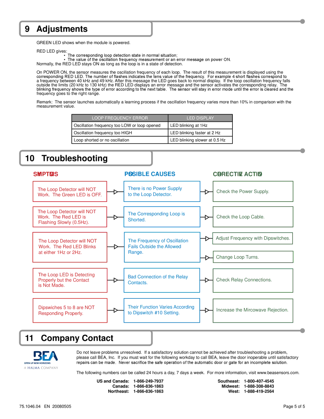
On POWER ON, the sensor measures the oscillation frequency of each loop. The result of this measurement is displayed using the corresponding RED LED. The number of flashes indicates the tens value of the frequency. For example 4 short flashes correspond to a frequency between 40 kHz and 49 kHz. After this message the LED goes back to normal display. If the loop oscillation frequency falls outside the limits (20 kHz to 130 kHz) the RED LED displays an error message and the sensor activates the corresponding relay. The blinking frequency shows the type of error according to the next table. The sensor will stay in error mode until the error is cleared and the frequency goes to the right range.
Remark: The sensor launches automatically a learning process if the oscillation frequency varies more than 10% in comparison with the measurement value.
LOOP FREQUENCY ERROR | LED DISPLAY |
Oscillation frequency too LOW or loop opened | LED blinking at 1Hz |
Oscillation frequency too HIGH | LED blinking faster at 2 Hz |
|
|
Loop shorted or no oscillation | LED blinking slower at 0.5 Hz |
10 Troubleshooting
SYMPTOMS
The Loop Detector will NOT
Work. The Green LED is OFF.
The Loop Detector will NOT
Work. The Red LED is
Flashing Slowly (0.5Hz).
The Loop Detector will NOT Work. The Red LED Blinks at either 1Hz or 2Hz.
The Loop LED is Detecting Properly but the Contact is Not Made.
Dipswiches 5 to 8 are NOT
Responding Properly.
POSSIBLE CAUSES
There is no Power Supply to the Loop Detector.
The Corresponding Loop is Shorted.
The Frequency of Oscillation
Fails Outside the Allowed
Range.
Bad Connection of the Relay Contacts.
Their Function Varies According to Dipswitch #10 Setting.
CORRECTIVE ACTION
Check the Power Supply.
Check the Loop Cable.
Adjust Frequency with Dipswitches.
Change Loop Turns.
Check Relay Connections.
Increase the Mircowave Rejection.
11 Company Contact
Do not leave problems unresolved. If a satisfactory solution cannot be achieved after troubleshooting a problem, please call BEA, Inc. If you must wait for the following workday to call BEA, leave the door inoperable until satisfactory repairs can be made. Never sacrifice the safe operation of the automatic door or gate for an incomplete solution.
The following numbers can be called 24 hours a day, 7 days a week. For more information, visit www.beasensors.com.
US and Canada: | Southeast: | ||
Canada: | Midwest: | ||
Northeast: | West: | ||
75.1046.04 EN 20080505 | Page 5 of 5 |
