7 Programming (cont’d)
IV. DIPSWITCHES
A. After each dipswitch change the sensor launches a learning process.
DIPSWITCH | LEARNING PROCESS |
|
#1 | Frequency Adjustments of Loop A (see ADJUSTMENTS) | |
#2 | Frequency Adjustments of Loop A (with single loop) or Loop B (with Dual Loops) | |
#3 | Relay configuration: Active | |
|
| |
#4 | Automatic Sensitivity Boost (ASB option) [recommended for improved truck detection] : | |
| During a detection, the sensitivity increases automatically to 8 times the preset sensitivity given by the sensitivity | |
|
| Δ |
| potentiometer adjustment. It is limited to the maximum sensitivity ( f = 0.005%). It goes back to the preset value after | |
| detection stops. |
|
#5 | Relay A Function: Presence or Pulse | (not used with dual loop in combined mode) |
|
| |
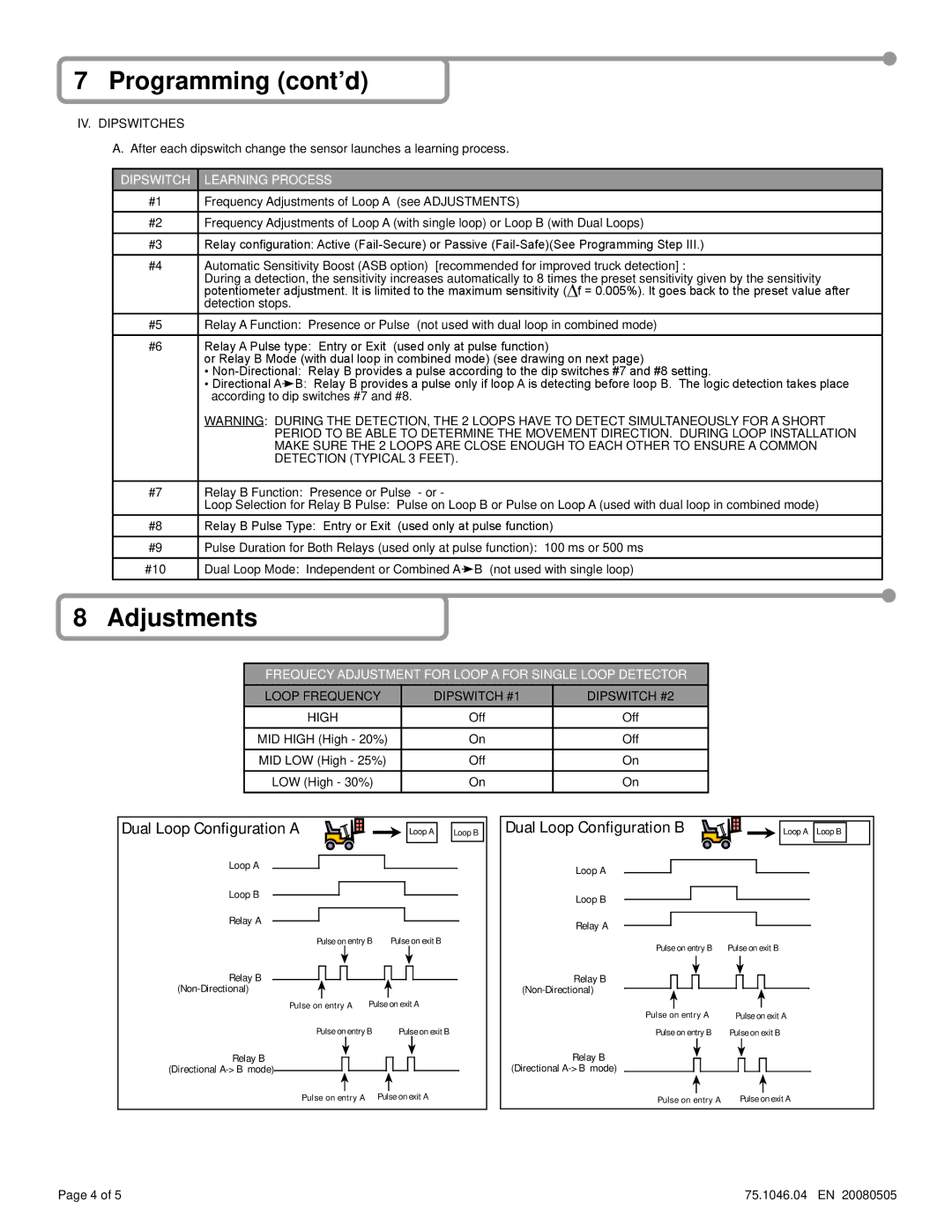
#6 | Relay A Pulse type: Entry or Exit (used only at pulse function) | |
| or Relay B Mode (with dual loop in combined mode) (see drawing on next page) | |
| • | |
| • Directional A B: Relay B provides a pulse only if loop A is detecting before loop B. The logic detection takes place | |
| according to dip switches #7 and #8. |
|
| WARNING: DURING THE DETECTION, THE 2 LOOPS HAVE TO DETECT SIMULTANEOUSLY FOR A SHORT | |
| PERIOD TO BE ABLE TO DETERMINE THE MOVEMENT DIRECTION. DURING LOOP INSTALLATION | |
| MAKE SURE THE 2 LOOPS ARE CLOSE ENOUGH TO EACH OTHER TO ENSURE A COMMON | |
| DETECTION (TYPICAL 3 FEET). | |
|
|
|
#7 | Relay B Function: Presence or Pulse | - or - |
| Loop Selection for Relay B Pulse: Pulse on Loop B or Pulse on Loop A (used with dual loop in combined mode) | |
#8 | Relay B Pulse Type: Entry or Exit (used only at pulse function) | |
#9 | Pulse Duration for Both Relays (used only at pulse function): 100 ms or 500 ms | |
#10 | Dual Loop Mode: Independent or Combined A B (not used with single loop) | |
8 Adjustments
FREQUECY ADJUSTMENT FOR LOOP A FOR SINGLE LOOP DETECTOR
LOOP FREQUENCY | DIPSWITCH #1 | DIPSWITCH #2 |
HIGH | Off | Off |
MID HIGH (High - 20%) | On | Off |
MID LOW (High - 25%) | Off | On |
LOW (High - 30%) | On | On |
|
|
|
|
|
|
|
|
|
|
|
|
|
|
|
|
|
|
Dual Loop Configuration A |
|
|
|
|
|
|
|
|
| |||||
|
|
|
|
| Loop A |
| Loop B |
| ||||||
Loop A |
|
|
|
|
|
|
|
|
|
|
|
|
|
|
|
|
|
|
|
|
|
|
|
|
|
|
|
| |
|
|
|
|
|
|
|
|
| ||||||
Loop B |
|
|
|
|
|
|
|
|
|
|
|
| ||
|
|
|
|
|
|
|
|
|
|
|
|
| ||
|
|
|
|
|
|
|
| |||||||
Relay A |
|
|
|
|
|
|
|
|
|
|
|
| ||
|
|
|
|
|
|
|
|
|
|
|
|
| ||
| Pulse on exit B | |||||||||||||
|
| Pulse on entry B | ||||||||||||
Relay B |
|
|
|
|
|
|
|
|
|
|
|
| |||
|
| Pulse |
| on exit A | |||||||||||
|
|
| |||||||||||||
|
| Pulse on | entry A |
| |||||||||||
|
| Pulse on entry B |
|
|
| Pulse on exit B | |||||||||
Relay B |
|
|
|
|
|
|
|
|
|
| |||||
|
|
|
|
|
|
|
|
|
| ||||||
(Directional |
|
|
|
|
|
|
|
|
|
|
|
|
|
| |
|
|
|
|
|
|
|
|
|
|
|
| ||||
|
|
|
|
|
|
| |||||||||
|
|
|
|
|
|
|
| ||||||||
|
| Pulse on entry A |
| Pulse on exit A | |||||||||||
|
|
|
|
|
|
|
|
|
|
|
|
|
|
| ||||||||||
Dual Loop Configuration B |
|
|
|
|
|
|
| Loop A | Loop B |
|
| |||||||||||||
Loop A |
|
|
|
|
|
|
|
|
|
|
|
|
|
|
|
|
|
|
|
|
|
|
|
|
|
|
|
|
|
|
|
|
|
|
|
|
|
|
|
|
|
|
|
|
|
|
|
| |
|
|
|
|
|
|
|
|
|
|
|
|
|
|
|
|
|
|
|
|
|
|
|
| |
|
|
|
|
|
|
|
|
|
|
|
|
|
|
|
|
|
|
|
|
|
|
|
| |
|
|
|
|
|
|
|
|
|
|
|
|
|
|
| ||||||||||
Loop B |
|
|
|
|
|
|
|
|
|
|
|
|
|
|
|
|
|
|
|
|
| |||
|
|
|
|
|
|
|
|
|
|
|
|
|
|
|
|
|
|
|
|
|
|
| ||
|
|
|
|
|
|
|
|
|
|
|
|
|
|
| ||||||||||
Relay A |
|
|
|
|
|
|
|
|
|
|
|
|
|
|
|
|
|
| ||||||
|
|
|
|
|
|
|
|
|
|
|
|
|
|
|
|
|
|
|
| |||||
| Pulse on exit B | |||||||||||||||||||||||
|
| Pulse on entry B | ||||||||||||||||||||||
Relay B |
|
|
|
|
|
|
|
|
|
|
|
|
|
|
|
|
|
|
|
|
| |||
|
|
|
|
|
|
|
|
|
|
|
|
|
|
|
|
|
|
|
|
| ||||
|
|
|
|
|
|
|
|
|
|
|
|
|
|
|
|
|
|
|
|
| ||||
|
|
|
|
|
|
|
|
|
|
|
|
|
|
|
|
|
|
|
|
|
| |||
|
|
|
|
|
|
|
|
|
|
|
|
|
|
|
|
|
|
|
|
|
| |||
|
|
|
|
|
|
|
|
|
|
|
|
|
|
|
| |||||||||
|
|
|
|
|
|
|
|
|
|
|
|
|
|
|
|
| ||||||||
|
| Pulse on entry A |
| Pulse on exit A | ||||||||||||||||||||
|
| Pulse on entry B | Pulse on exit B | |||||||||||||||||||||
Relay B |
|
|
|
|
|
|
|
|
|
|
|
|
|
|
|
| ||||||||
|
|
|
|
|
|
|
|
|
|
|
|
|
|
|
| |||||||||
(Directional |
|
|
|
|
|
|
|
|
|
|
|
|
|
|
|
|
| |||||||
|
|
|
|
| Pulse |
|
|
|
|
|
|
| ||||||||||||
|
| Pulse on |
| entry A |
|
|
|
|
|
|
|
|
| |||||||||||
|
|
|
|
| on exit A | |||||||||||||||||||
|
|
|
|
|
|
|
|
|
|
|
|
|
|
|
|
|
|
|
|
|
|
|
|
|
Page 4 of 5 | 75.1046.04 EN 20080505 |