005028-0, 005030-0, 005028-0, 005031-0 specifications
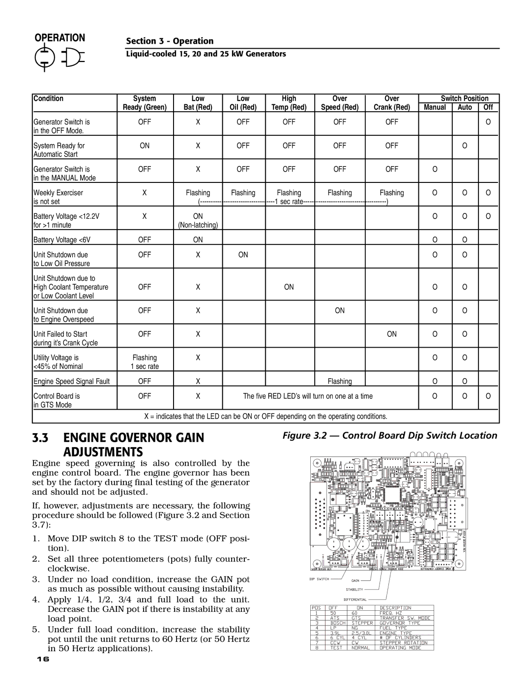
Generac's line of generator models, including the 005028-0, 005030-0, 005031-0, and their closely related variant 005028-0, represent a fusion of durability, technology, and user-centric design focused on providing reliable power solutions for residential and commercial applications.The Generac 005028-0 model stands out with its robust construction and efficient performance. It features a powerful engine that ensures a steady supply of electricity, capable of handling essential appliances during power outages. The model incorporates Generac's patented TruePower technology, which offers clean and stable power, ensuring sensitive electronics are safe from fluctuations. This feature is particularly appealing for homeowners who rely on medical equipment or sophisticated devices that require consistent power quality.
On the other hand, the 005030-0 model takes performance up a notch by equipped with a larger fuel tank, allowing for extended runtime during outages. It also has a quieter operation compared to its counterparts, making it suitable for residential areas where noise levels are a concern. The model includes an intuitive user interface that simplifies operation, letting users monitor their generator’s status effortlessly.
Similarly, the 005031-0 model boasts enhanced technology via a fully automatic transfer switch. This feature enables seamless switching between utility power and generator power without user intervention, ensuring that homes and businesses remain powered even during unexpected power failures. Equipped with advanced safety features, this model ensures that the generator operates only when necessary, significantly extending its lifespan and maintaining efficiency.
Additionally, all these Generac models share a durable casing designed to withstand harsh weather conditions. They are engineered for easy maintenance, with oil and fuel access points conveniently located for user convenience. Furthermore, the models come with various options for fuel types, including propane and natural gas, providing users flexibility based on their needs.
In summary, Generac's 005028-0, 005030-0, and 005031-0 models are characterized by their reliable performance, advanced technology, and user-friendly features. These generators are perfect solutions for anyone seeking a dependable source of backup power, ensuring that essential equipment runs smoothly without interruptions, no matter the situation.

