4 FCC Compliance
FCC ID#: G9B-MATRIX IC ID#: 4680A-MATRIX
10MATRIXS110 | : Single loop detector with 110 to 120 V AC power supply. |
10MATRIXS220 | : Single loop detector with 220 to 240 V AC power supply. |
10MATRIXS1224 : Single loop detector with 12 to 24 V AC/DC power supply. | |
10MATRIXD110 | : Dual loop detector with 110 to 120 V AC power supply. |
10MATRIXD220 | : Dual loop detector with 220 to 240 V AC power supply. |
10MATRIXD1224 : Dual loop detector with 12 to 24 V AC/DC power supply.
The Digital Transmitters and Receivers comply with Part 15 of the FCC rules. Operation is subject to the following two conditions:
1)This device may not cause harmful interference and;
2)This device must accept any interference received including interference that may cause undesired operations.
Changes or modifications not expressly approved by BEA, Inc. for compliance could void the user’s authority to operate the equipment.
5 Loop Installation Tips
A . CABLE SPECIFICATIONS FOR LOOP AND FEEDER
•16 AWG (1.5mm²) cross section area ;
•
•Insulation material : PVC or Silicone ;
•For the feeder cable, the wire must be twisted at least 15 times per yard for each cable.
•Feeder for long runs used for foil screened cable is recommended (earth at equipment end only)
•The feeder cable must be firmly fixed to avoid any false detection (max length: 330 ft. / 100m).
•Waterproof cable junction box is required.
B. LOOP GEOMETRY
L |
Ea |
Eb |
•When two adjacent loops are connected to a dual channel sensor, it is possible for these loops to share a common slot, if so required. As the channels are multiplexed, no interference will occur.
•Avoid large loops or long feeder (max 330 ft. / 100 m), or else the sensitivity will be affected.
C. NUMBER OF LOOP TURNS
• Measure the length (L) and width (Ea) of one loop. Multiply these numbers together to determine the loop surface area.
• For example: If L=10 ft, Ea= 3 ft, then the area = 30 ft2; 4 loop turns are recommended - or - If L=2m, Ea=1m, then the area = 2 m2 ; 4 loop turns are recommended.
WARNING: FOR CONFORMITY REASONS, IN ANY INSTALLATION, THE LOOP SURFACE MULTIPLIED BY THE NUMBER OF TURNS SHOULD NOT EXCEED 215 SQUARE FEET OR 20 SQUARE METERS.
Recommended values for the turns: | Area |
| Number of turns |
| <32 ft² | <3 m² | 4 |
|
|
|
|
| 32 – 54 ft² | 3 – 5 m² | 3 |
|
|
|
|
| 65 – 108 ft² | 6 – 10 m² | 2 |
D. SLOT DEPTH
Ground ![]() level
level![]()
![]()
Loop sealant
1 ¼ - 2” (30 – 50mm) depending on the cable turns number
Clean and dry slots prior to inserting cable
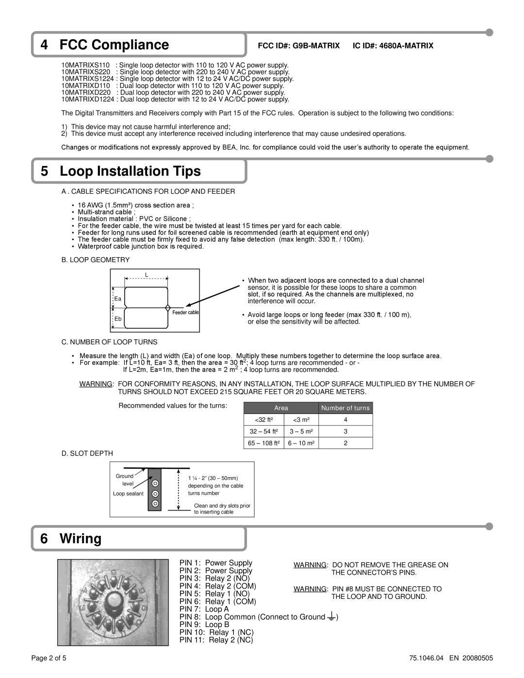
6 Wiring
PIN 1: Power Supply | WARNING: DO NOT REMOVE THE GREASE ON | ||||
PIN 2: Power Supply |
|
| THE CONNECTOR’S PINS. | ||
PIN 3: Relay 2 (NO) |
|
|
|
| |
PIN 4: Relay 2 (COM) | WARNING: PIN #8 MUST BE CONNECTED TO | ||||
PIN 5: Relay 1 (NO) | |||||
|
| THE LOOP AND TO GROUND. | |||
PIN 6: Relay 1 (COM) |
|
| |||
|
|
|
| ||
PIN 7: Loop A |
|
|
|
| |
PIN 8: Loop Common (Connect to Ground |
|
| ) | ||
PIN 9: Loop B |
|
|
|
| |
PIN 10: Relay 1 (NC) |
|
|
|
| |
PIN 11: Relay 2 (NC) |
|
|
|
| |
Page 2 of 5 | 75.1046.04 EN 20080505 |