7
the crated boiler to the carrier in good condition. ANY CLAIMS FOR DAMAGE OR SHORTAGE IN SHIPMENT MUST BE FILED IMMEDIATELY against the carrier by the consignee.
Temperature Controls Installation and Adjustment
1.After cabinet installation is complete install the temperature control on the right side of the boiler.
a)Carlin Aquastat – Attach the 4 x 4 Junction box supplied with the Carlin control using the 1/2” electrical box connector attached to the side of the jacket.
b)Honeywell L7248A1000 – Remove sensor wires which are fed through the 1/2” box connector.
Attach the aquastat to the 1/2” box connector. Remove jacket top panel. Loosen and remove the wire clamp on the immersion well and remove sensor wires from the immersion well. Run the sensor lead through the aquastat and reinstall into the immersion well. Replace the wire clamp and tighten to secure sensor leads in the immersion well.
c)Honeywell L7248C1022 – Remove sensor wires which are fed through the 1/2” box connector. Remove the 1/2” box connector from the jacket side panel and insert the Heyco bushing in the hole. Run the sensor wires through the hole in the jacket panel. Attach the aquastat to the jacket side panel using sheet metal screws and the holes provided in the jacket panel. The sensor wires should be run through the bottom knockout in the aquastat. The rubber grommet provided with the sensor wires is to be securely inserted into the aquastat knockout.
2.Connect the sensor leads to the appropriate temperature control terminals.
3.Connect your line voltage and thermostat wires if applicable to the control. See electrical diagrams for proper connections.
4.Honeywell L7248 - The overall range of the High Limit is from 1300F to 2200F. Typically it would be set in the range of 1800F to 2000F.
5.Carlin 90200A- A manually adjusted potentiometer is used to set the High Limit, typically it would be set in the range of 180oF to 200oF. The high limit differential is preset to 250F
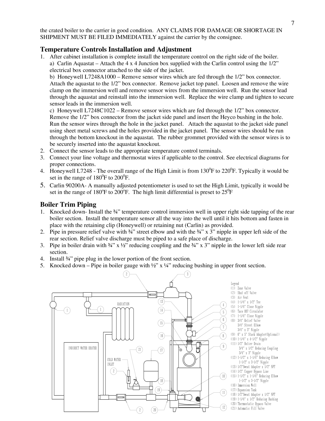
Boiler Trim Piping
1.Knocked down- Install the ¾” temperature control immersion well in upper right side tapping of the rear boiler section. Install the temperature sensor all the way into the well until it hits bottom and fasten in place with the retaining clip (Honeywell) or retaining nut (Carlin) as provided.
2.Pipe in pressure relief valve with ¾” street elbow and with the ¾” x 3” nipple in upper left side of the rear section. Relief valve discharge must be piped to a safe place of discharge.
3.Pipe in boiler drain with ¾” x ½” reducing coupling and the ¾” x 3” nipple in the lower left side rear section.
4.Install ¾” pipe plug in the lower portion of the front section.
5.Knocked down – Pipe in boiler gauge with ½” x ¼” reducing bushing in upper front section.