Behringer PROMIC2200 manual Control Elements, Front panel control elements

Models: PROMIC2200

1 20
Download 20 pages 14.49 Kb
Page 13
Image 13
4. CONTROL ELEMENTS

ULTRAGAIN PRO MIC2200

+Never use unbalanced XLR connections with microphone cables, as this would short-circuit any phantom power transmitted over these cables!

4. CONTROL ELEMENTS

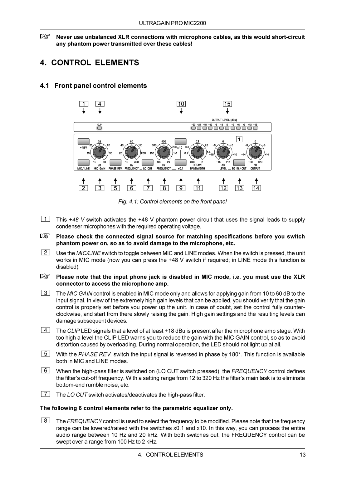
4.1 Front panel control elements

Fig. 4.1: Control elements on the front panel

1

This +48 V switch activates the +48 V phantom power circuit that uses the signal leads to supply condenser microphones with the required operating voltage.

+Please check the connected signal source for matching specifications before you switch phantom power on, so as to avoid damage to the microphone, etc.

2

Use the MIC/LINE switch to toggle between MIC and LINE modes. When the switch is pressed, the unit works in MIC mode (now you can press the +48 V switch if required; in LINE mode this function is disabled).

+Please note that the input phone jack is disabled in MIC mode, i.e. you must use the XLR connector to access the microphone amp.

3

The MIC GAIN control is enabled in MIC mode only and allows for applying gain from 10 to 60 dB to the input signal. In view of the extremely high gain levels that can be applied, you should verify that the gain control is properly set before you power up the unit. In case of doubt, set the control fully counter- clockwise, and start from there slowly raising the gain. High gain settings and the resulting levels can damage subsequent devices.

4

5

6

7

The CLIP LED signals that a level of at least +18 dBu is present after the microphone amp stage. With too high a level the CLIP LED warns you to reduce the gain with the MIC GAIN control, so as to avoid distortion caused by overloading. During normal operation, the LED should not light up at all.

With the PHASE REV. switch the input signal is reversed in phase by 180°. This function is available both in MIC and LINE modes.

When the high-pass filter is switched on (LO CUT switch pressed), the FREQUENCY control defines the filter’s cut-off frequency. With a setting range from 12 to 320 Hz the filter’s main task is to eliminate bottom-end rumble noise, etc.

The LO CUT switch activates/deactivates the high-pass filter.

The following 6 control elements refer to the parametric equalizer only.

8

The FREQUENCY control is used to select the frequency to be modified. Please note that the frequency range can be lowered/raised with the switches x0.1 and x10. In this way, you can process the entire audio range between 10 Hz and 20 kHz. With both switches out, the FREQUENCY control can be swept over a range from 100 Hz to 2 kHz.

4. CONTROL ELEMENTS

13

Page 13
Image 13
Behringer PROMIC2200 manual Control Elements, Front panel control elements, 1 Control elements on the front panel