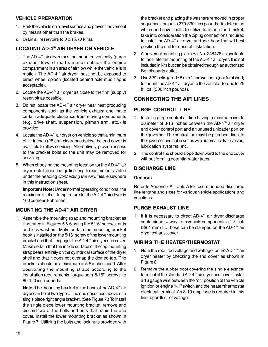
BW1450 specifications
The BENDIX BW1450 is a highly regarded air brake system that delivers exceptional performance and reliability in the heavy-duty truck and automotive sectors. The BW1450 is designed with advanced technologies and engineering breakthroughs that ensure enhanced safety and efficiency in braking operations.One of the standout features of the BENDIX BW1450 is its robust and compact design. Constructed to withstand the rigors of heavy use, the system is both lightweight and durable, allowing for easy installation and maintenance. It incorporates a corrosion-resistant finish that helps protect against environmental factors, ensuring longevity and dependability.
The BW1450 leverages advanced modulation technology, which provides superior control during braking. This technology allows for gradual engagement and disengagement of the brakes, significantly reducing the risk of skidding or jackknifing during emergency stops. The system's sophistication extends to its ability to maintain consistent brake performance under various load conditions, making it a versatile choice for different vehicle types.
Another significant characteristic of the BENDIX BW1450 is its integrated Air Disc Brake technology. This feature not only improves the overall stopping power but also results in shorter stopping distances. In addition to enhanced performance, the air disc brakes are easier to maintain compared to traditional drum brakes, reducing downtime and service costs.
The BENDIX BW1450 also incorporates smart sensor technologies that monitor brake performance, providing real-time data to drivers and fleet operators. This capability enhances fleet management as it allows for timely maintenance interventions and ensures that the braking system operates optimally at all times.
Safety is a paramount concern in any braking system, and the BENDIX BW1450 is equipped with an anti-lock braking system (ABS). This feature prevents wheel lock-up during hard braking, thus providing additional control in slippery conditions and enhancing the vehicle's stability. Moreover, the system meets or exceeds various industry safety standards, reinforcing its position as a reliable choice for heavy-duty applications.
In conclusion, the BENDIX BW1450 air brake system represents a combination of innovative design, cutting-edge technology, and reliable performance. Its lightweight construction, advanced modulation control, air disc braking capabilities, and integrated safety features make it an exemplary choice for the demanding requirements of heavy-duty vehicles.
