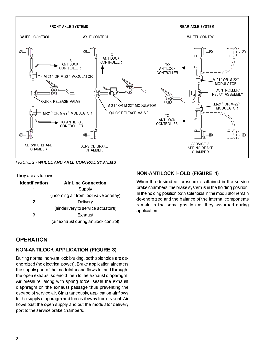
FRONT AXLE SYSTEMS |
| REAR AXLE SYSTEM | ||
WHEEL CONTROL | AXLE CONTROL | WHEEL CONTROL | ||
|
| TO |
| |
| TO | ANTILOCK |
| |
| CONTROLLER |
| ||
| ANTILOCK | TO | ||
| CONTROLLER |
| ANTILOCK | |
| CONTROLLER | |||
| ||||
|
|
| ||
|
|
| MODULATOR | |
|
|
| CONTROLLER/ | |
|
|
| RELAY ASSEMBLY | |
QUICK RELEASE VALVE | ||||
|
| |||
QUICK RELEASE VALVE | MODULATOR | |||
TO | ||||
|
|
| ||
| TO ANTILOCK |
| ANTILOCK | |
| CONTROLLER | |||
| CONTROLLER | |||
|
|
| ||
|
| bw |
| |
SERVICE BRAKE | SERVICE BRAKE | SERVICE & | ||
CHAMBER | CHAMBER | SPRING BRAKE | ||
|
|
| CHAMBER | |
FIGURE 2 - WHEEL AND AXLE CONTROL SYSTEMS
They are as follows;
Identification | Air Line Connection |
1 | Supply |
| (incoming air from foot valve or relay) |
2 | Delivery |
| (air delivery to service actuators) |
3 | Exhaust |
| (air exhaust during antilock control) |
NON-ANTILOCK HOLD (FIGURE 4)
When the desired air pressure is attained in the service brake chambers, the brake system is in the holding position. In the holding position both solenoids in the modulator remain
OPERATION
NON-ANTILOCK APPLICATION (FIGURE 3)
During normal
2