| EXHAUST | EXHAUST |
| SOLENOID | |
| DIAPHRAGM | |
|
| |
EXHAUST PORT |
|
|
|
| BRAKE VALVE |
|
| SUPPLY |
|
| SOLENOID |
BRAKE | SUPPLY | SPRING |
SPRING | ||
CHAMBER | DIAPHRAGM |
|
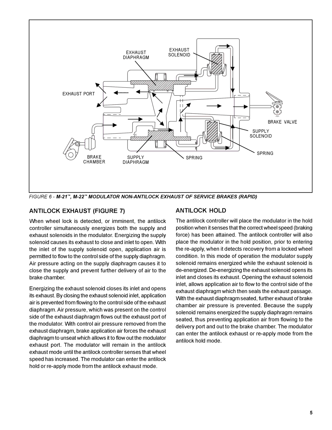
FIGURE 6 - | ||
ANTILOCK EXHAUST (FIGURE 7)
When wheel lock is detected, or imminent, the antilock controller simultaneously energizes both the supply and exhaust solenoids in the modulator. Energizing the supply solenoid causes its exhaust to close and inlet to open. With the inlet of the supply solenoid open, application air is permitted to flow to the control side of the supply diaphragm. Air pressure acting on the supply diaphragm causes it to close the supply and prevent further delivery of air to the brake chamber.
Energizing the exhaust solenoid closes its inlet and opens its exhaust. By closing the exhaust solenoid inlet, application air is prevented from flowing to the control side of the exhaust diaphragm. Air pressure, which was present on the control side of the exhaust diaphragm flows out the exhaust port of the modulator. With control air pressure removed from the exhaust diaphragm, brake application air forces the exhaust diaphragm to unseat which allows it to flow out the modulator exhaust port. The modulator will remain in the antilock exhaust mode until the antilock controller senses that wheel speed has increased. The modulator can enter the antilock hold or
ANTILOCK HOLD
The antilock controller will place the modulator in the hold position when it senses that the correct wheel speed (braking force) has been attained. The antilock controller will also place the modulator in the hold position, prior to entering the
5
