| EXHAUST | EXHAUST |
| SOLENOID | |
| DIAPHRAGM | |
|
| |
EXHAUST PORT |
|
|
|
| BRAKE VALVE |
|
| SUPPLY |
|
| SOLENOID |
BRAKE | SUPPLY | SPRING |
SPRING | ||
CHAMBER | DIAPHRAGM |
|
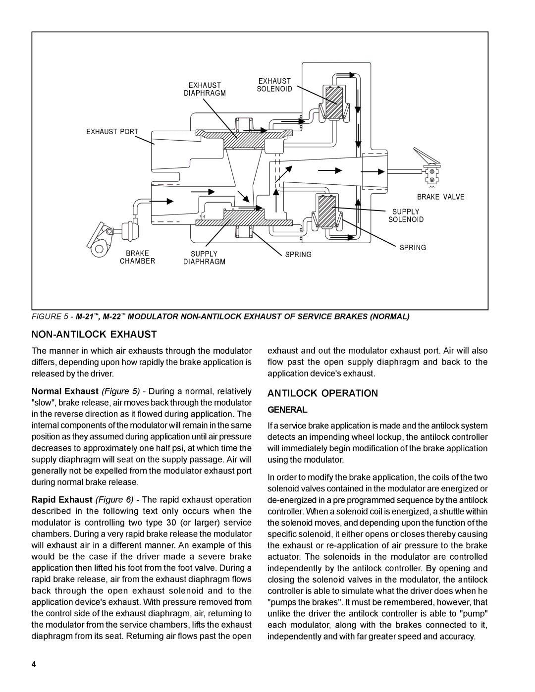
FIGURE 5 - | ||
NON-ANTILOCK EXHAUST
The manner in which air exhausts through the modulator differs, depending upon how rapidly the brake application is released by the driver.
Normal Exhaust (Figure 5) - During a normal, relatively "slow", brake release, air moves back through the modulator in the reverse direction as it flowed during application. The internal components of the modulator will remain in the same position as they assumed during application until air pressure decreases to approximately one half psi, at which time the supply diaphragm will seat on the supply passage. Air will generally not be expelled from the modulator exhaust port during normal brake release.
Rapid Exhaust (Figure 6) - The rapid exhaust operation described in the following text only occurs when the modulator is controlling two type 30 (or larger) service chambers. During a very rapid brake release the modulator will exhaust air in a different manner. An example of this would be the case if the driver made a severe brake application then lifted his foot from the foot valve. During a rapid brake release, air from the exhaust diaphragm flows back through the open exhaust solenoid and to the application device's exhaust. With pressure removed from the control side of the exhaust diaphragm, air, returning to the modulator from the service chambers, lifts the exhaust diaphragm from its seat. Returning air flows past the open
exhaust and out the modulator exhaust port. Air will also flow past the open supply diaphragm and back to the application device's exhaust.
ANTILOCK OPERATION
GENERAL
If a service brake application is made and the antilock system detects an impending wheel lockup, the antilock controller will immediately begin modification of the brake application using the modulator.
In order to modify the brake application, the coils of the two solenoid valves contained in the modulator are energized or
4