As the potentiometer rotates, its resistance changes. This way, the potentiometer can react to the driver’s request for engine power through the
The electronic treadle receives its supply voltage from the engine control unit. If the driver does not request engine power, the treadle is in the idle position. This condition is also referred to as “Closed Throttle.” In this state, the potentiometer returns the minimum percentage of supply voltage to the engine control unit (see Figure 2).
As the driver depresses the treadle, the electronic treadle output voltage increases (see Figure 3). The potentiometer allows an increased amount of its supply voltage to return to the engine control unit, which in turn increases the engine’s speed.
In the full, or “Open Throttle” position, the driver has depressed the treadle to its furthest possible point. This is the state of least potentiometer resistance. The electronic treadle returns the maximum percentage of supply voltage to the engine control unit (see Figure 2).
PREVENTIVE MAINTENANCE
Important: Review the warranty policy before performing any intrusive maintenance procedures. An extended warranty may be voided if intrusive maintenance is performed during this period.
Because no two vehicles operate under identical conditions, maintenance intervals will vary. Experience is a valuable guide in determining the best maintenance interval for a vehicle.
GENERAL
Important: Visually check for physical damage to the electronic treadle such as broken or missing parts. Actuate the pedal five times from stop to stop, noting any binding or soft pedal response.
Important Note: DO NOT DISASSEMBLE THE ACTUATOR
BODY. Replace the
2
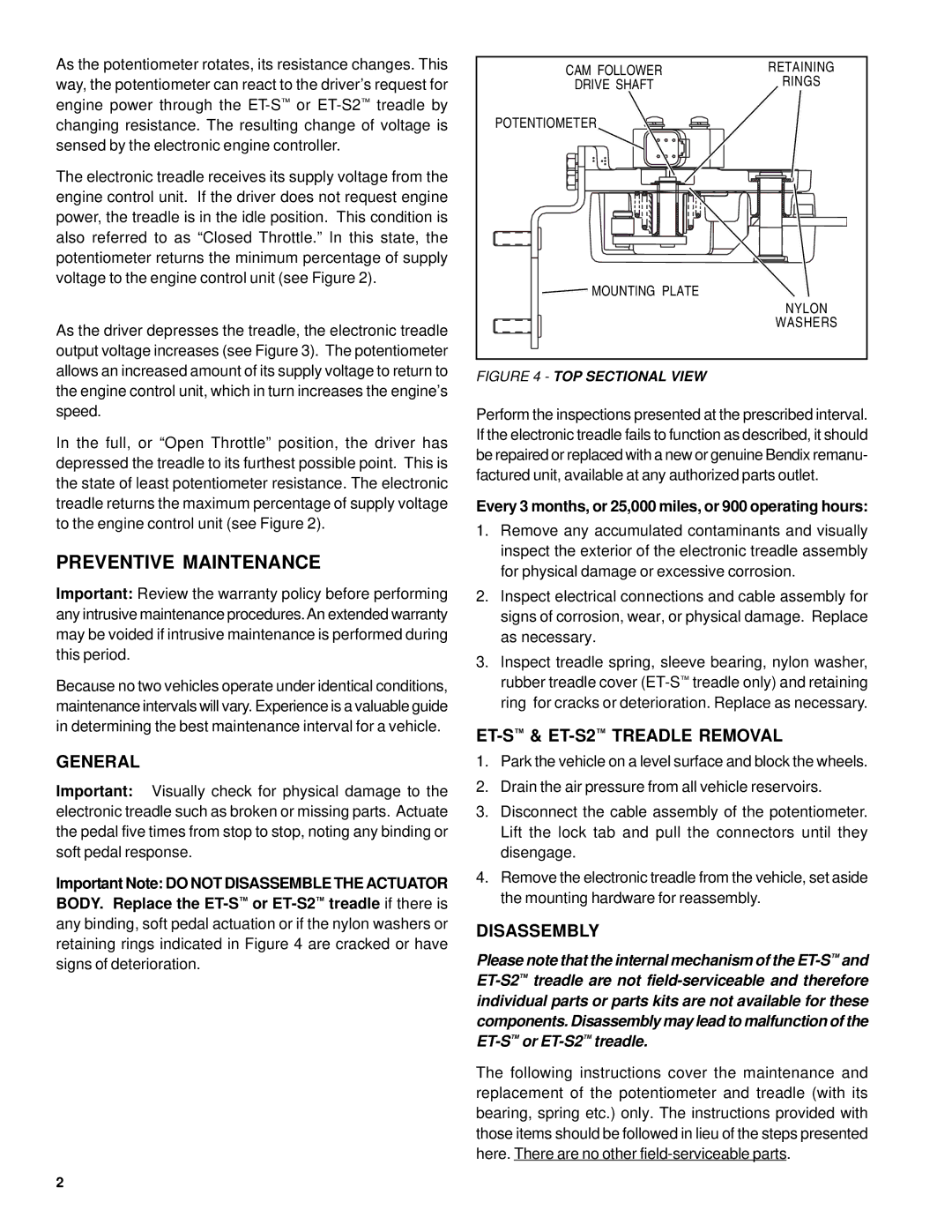
CAM FOLLOWER | RETAINING |
DRIVE SHAFT | RINGS |
POTENTIOMETER |
|
MOUNTING PLATE |
|
| NYLON |
| WASHERS |
FIGURE 4 - TOP SECTIONAL VIEW
Perform the inspections presented at the prescribed interval. If the electronic treadle fails to function as described, it should be repaired or replaced with a new or genuine Bendix remanu- factured unit, available at any authorized parts outlet.
Every 3 months, or 25,000 miles, or 900 operating hours:
1.Remove any accumulated contaminants and visually inspect the exterior of the electronic treadle assembly for physical damage or excessive corrosion.
2.Inspect electrical connections and cable assembly for signs of corrosion, wear, or physical damage. Replace as necessary.
3.Inspect treadle spring, sleeve bearing, nylon washer, rubber treadle cover
ET-S™ & ET-S2™ TREADLE REMOVAL
1.Park the vehicle on a level surface and block the wheels.
2.Drain the air pressure from all vehicle reservoirs.
3.Disconnect the cable assembly of the potentiometer. Lift the lock tab and pull the connectors until they disengage.
4.Remove the electronic treadle from the vehicle, set aside the mounting hardware for reassembly.
DISASSEMBLY
Please note that the internal mechanism of the
The following instructions cover the maintenance and replacement of the potentiometer and treadle (with its bearing, spring etc.) only. The instructions provided with those items should be followed in lieu of the steps presented here. There are no other