3.Inspect the cable assembly for loose or frayed wires, physical damage, or any contaminants on the connec- tors. Replace as necessary.
ASSEMBLY
1.Securely clamp the treadle mounting plate.
2.(a) For Detroit Diesel Potentiometers: Align the drive slot, and engage the potentiometer the drive tang at the end of the drive shaft (see Figure 4). Rotate the
potentiometer clockwise until the first set of mounting holes align. Secure using two screws: torque to 25 (±5) in. lbs.
(b)For Caterpillar Position Sensor: Aligning the drive slot, the position sensor engages the drive tang at the end of the drive shaft (see Figure 4). Rotate the position sensor clockwise until the first set of mounting holes align. Secure using two screws : torque to 20 (±2) in. lbs.
DIGITAL |
|
VOLT/ |
|
OHM |
|
METER | POTENTIOMETER |
| PC. NO. ON THIS SURFACE |
POWER
SUPPLY
PIN C
300,000 OHM RESISTORGROUND TEST LOAD
PIN B | POTENTIOMETER |
VOUT |
|
(OUTPUT) |
|
PIN A
Closed Throttle (open) Range:
(INPUT)
Open Throttle (full) Range:
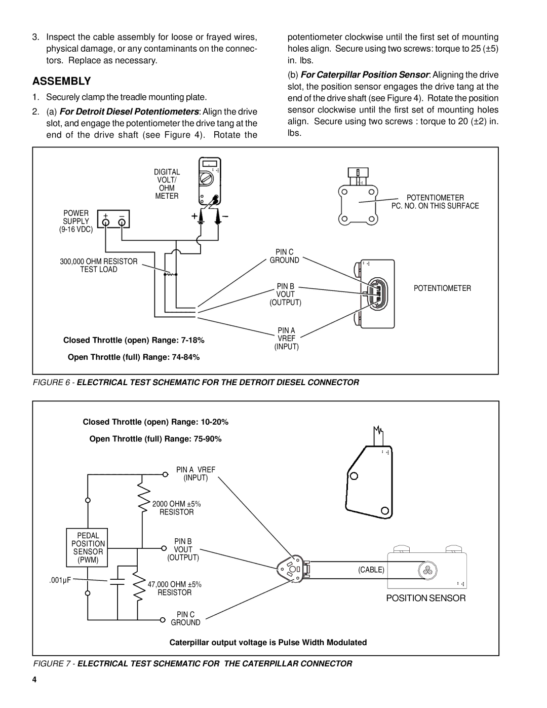
FIGURE 6 - ELECTRICAL TEST SCHEMATIC FOR THE DETROIT DIESEL CONNECTOR
Closed Throttle (open) Range:
Open Throttle (full) Range:
| PIN A VREF |
| (INPUT) |
| 2000 OHM ±5% |
| RESISTOR |
PEDAL | PIN B |
POSITION | |
SENSOR | VOUT |
(PWM) | (OUTPUT) |
| (CABLE) |
.001µF | 47,000 OHM ±5% |
| |
| RESISTOR |
| POSITION SENSOR |
| PIN C |
| GROUND |
| Caterpillar output voltage is Pulse Width Modulated |
FIGURE 7 - ELECTRICAL TEST SCHEMATIC FOR THE CATERPILLAR CONNECTOR
4