IDLE
VALIDATION
SWITCH
PEDAL
POSITION
SENSOR
IVS
|
| Vs | Closed Throttle (open) Range: | |||
DIODES |
| Open Throttle (full) Range: | ||||
|
| SUPPLY | ||||
TEST | TEST | VOLTAGE |
|
|
|
|
LOAD | LOAD |
| LOCK TAB |
|
|
|
470 | 470 |
|
|
|
|
|
PIN 6 OHM | OHM | V3 (LOGIC HIGH AT IDLE) |
|
|
| |
|
|
|
| POTENTIOMETER | ||
PIN 2 |
|
|
|
|
| |
| V2 (LOGIC LOW AT IDLE) |
|
| SET VOLTAGE | ||
|
|
|
| |||
PIN 1 |
|
|
|
|
| AND PC. NO. |
| IVS GROUND |
|
|
| SHOWN | |
|
|
|
|
| ||
|
|
|
|
|
| HERE |
|
|
|
| 5 |
|
|
|
|
|
| VS |
| |
|
|
| 4 | (INPUT) | 6 | |
|
| Vs | APS GROUND |
|
| (IVS) |
PIN 5 |
|
|
|
| V 3 | |
| SUPPLY |
|
|
| ||
|
| VOLTAGE |
|
|
|
|
PIN 3 |
| V1 |
|
|
|
|
PIN 4 | .01µ F | (OUTPUT) |
|
|
| LOCK TAB |
|
|
|
|
| ||
| APS |
|
|
|
| |
TEST LOAD |
|
|
|
| ||
GROUND | 3 |
|
| 1 | ||
47000 OHM |
| V1 |
|
| IVS GROUND | |
| 2 |
| ||||
|
|
| (OUTPUT) SIG1 |
|
| |
(IVS) V 2
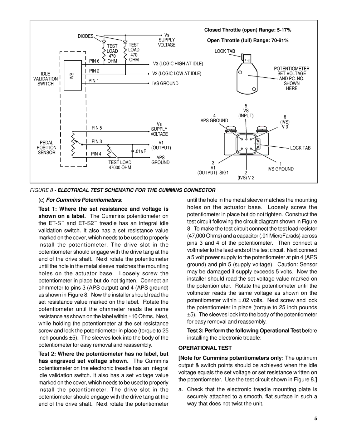
FIGURE 8 - ELECTRICAL TEST SCHEMATIC FOR THE CUMMINS CONNECTOR
(c)For Cummins Potentiometers:
Test 1: Where the set resistance and voltage is shown on a label. The Cummins potentiometer on the
Test 2: Where the potentiometer has no label, but
has engraved set voltage shown. The Cummins potentiometer on the electronic treadle has an integral idle validation switch. It also has a set voltage value marked on the cover, which needs to be used to properly install the potentiometer. The drive slot in the potentiometer should engage with the drive tang at the end of the drive shaft. Next rotate the potentiometer
until the hole in the metal sleeve matches the mounting holes on the actuator base. Loosely screw the potentiometer in place but do not tighten. Construct the test circuit following the circuit diagram shown in Figure
8.To make the test circuit connect the test load resistor (47,000 Ohms) and a capacitor (.01 MicroFarads) across pins 3 and 4 of the potentiometer. Then connect a voltmeter to the lead ends of the test circuit. Next connect a 5 volt power supply to the potentiometer at pin 4 (APS ground) and pin 5 (supply voltage). Caution: Sensor may be damaged if supply exceeds 5 volts. Now the installer should read the set voltage value marked on the potentiometer. Rotate the potentiometer until the voltmeter reads the same voltage as shown on the potentiometer within ±.02 volts. Next screw and lock the potentiometer in place (torque to 25 inch pounds ±5). The sleeves lock into the body of the potentiometer for easy removal and reassembly.
Test 3: Perform the following Operational Test before
installing the electronic treadle:
OPERATIONAL TEST
[Note for Cummins potentiometers only: The optimum output & switch points should be achieved when the idle voltage equals the set voltage or set resistance written on the potentiometer. Use the test circuit shown in Figure 8.]
a.Check that the electronic treadle mounting plate is securely attached to a smooth, flat surface in such a way that does not twist the unit.
5