| ACTUATOR |
|
|
| |
| BASE | 1 |
|
|
|
MOUNTING |
| POTENTIOMETER |
|
|
|
|
|
|
|
| |
PLATE |
| 2 |
|
|
|
|
|
|
|
| |
|
| #10 SCREWS |
|
| |
|
|
| 3 |
|
|
|
|
| RETAINING |
|
|
|
|
| RING |
|
|
|
|
| 4 |
|
|
|
|
| NYLON |
|
|
|
|
| WASHER |
|
|
ACTUATOR |
|
|
| TREADLE |
|
BODY |
|
|
|
| |
|
| 5 |
|
| |
|
|
|
|
| |
|
|
| REPLACEABLE |
| |
|
|
| RUBBER |
| |
| TREADLE |
| COVER |
| |
| 7 |
| |||
| ARM | ONLY) |
| ||
|
| SPRING |
| ||
|
| 6 |
|
| |
| PIVOT PIN | NYLINER |
|
| |
BEARING |
|
| |||
|
|
| PIVOT PIN | 6 | TREADLE |
|
|
| NYLINER | ||
|
|
|
| BEARING |
|
|
| TREADLE |
|
| |
|
|
| ARM |
| 4 |
|
|
|
|
| NYLON |
|
|
|
|
| WASHER |
|
|
|
|
| 3 |
|
|
|
|
| RETAINING |
|
|
|
|
| RING |
|
|
|
| 7 | |
|
|
|
| SPRING | TREADLE |
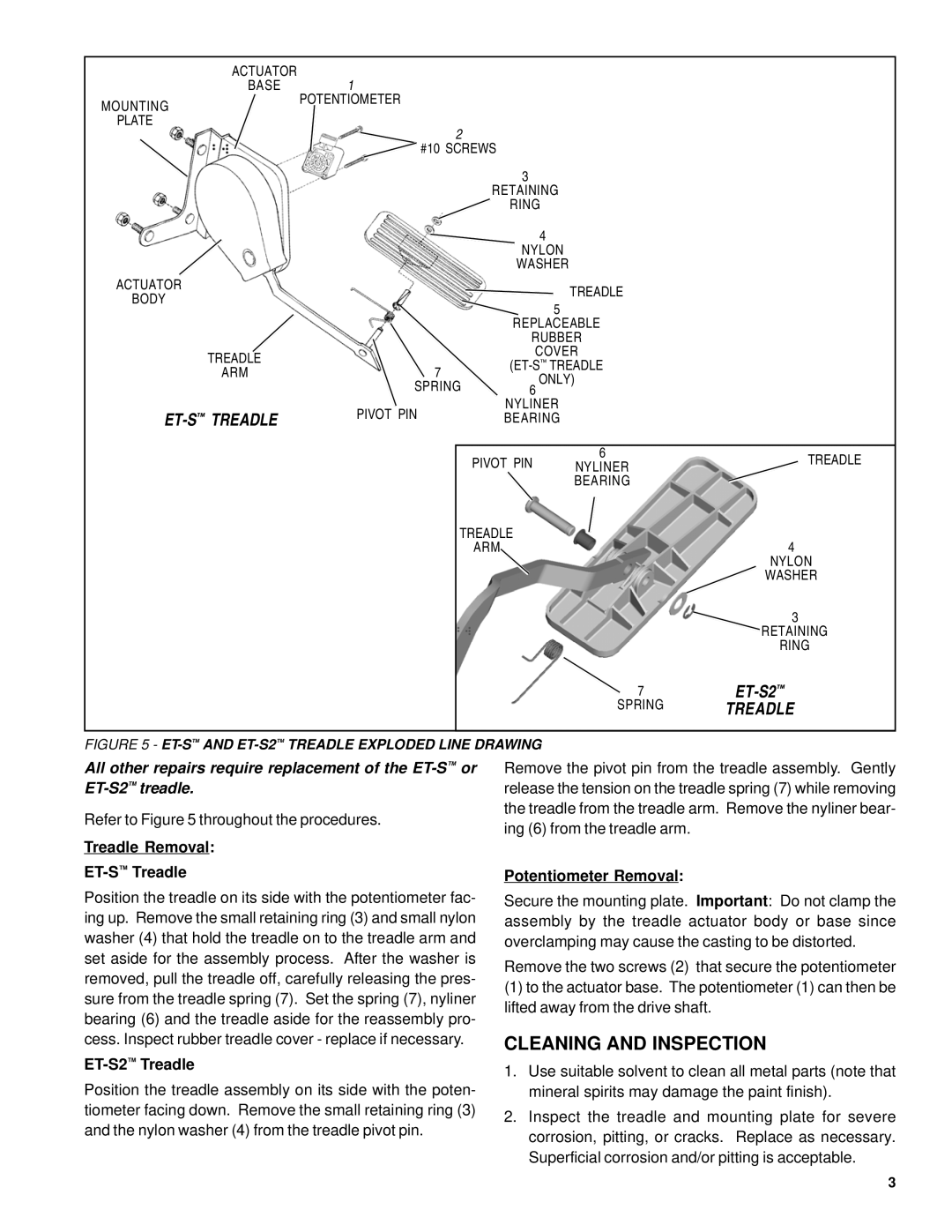
FIGURE 5 - | AND | TREADLE EXPLODED LINE DRAWING |
|
| |
All other repairs require replacement of the
Refer to Figure 5 throughout the procedures.
Treadle Removal:
ET-S™ Treadle
Position the treadle on its side with the potentiometer fac- ing up. Remove the small retaining ring (3) and small nylon washer (4) that hold the treadle on to the treadle arm and set aside for the assembly process. After the washer is removed, pull the treadle off, carefully releasing the pres- sure from the treadle spring (7). Set the spring (7), nyliner bearing (6) and the treadle aside for the reassembly pro- cess. Inspect rubber treadle cover - replace if necessary.
ET-S2™ Treadle
Position the treadle assembly on its side with the poten- tiometer facing down. Remove the small retaining ring (3) and the nylon washer (4) from the treadle pivot pin.
Remove the pivot pin from the treadle assembly. Gently release the tension on the treadle spring (7) while removing the treadle from the treadle arm. Remove the nyliner bear- ing (6) from the treadle arm.
Potentiometer Removal:
Secure the mounting plate. Important: Do not clamp the assembly by the treadle actuator body or base since overclamping may cause the casting to be distorted.
Remove the two screws (2) that secure the potentiometer
(1)to the actuator base. The potentiometer (1) can then be lifted away from the drive shaft.
CLEANING AND INSPECTION
1.Use suitable solvent to clean all metal parts (note that mineral spirits may damage the paint finish).
2.Inspect the treadle and mounting plate for severe corrosion, pitting, or cracks. Replace as necessary. Superficial corrosion and/or pitting is acceptable.
3