Status Lamp (Yellow)
Speed (NOT USED)
Ignition
12V Battery
J1939 High
J1939 Low
RESERVED
Vehicle Ground
Enable/Disable Switch
Warning Enabled Lamp (Green)
RESERVED
RESERVED
Left Turn Signal
Left Seat Vibrating Seat Motor (Optional) Right Speaker (+) (Optional)
Left Speaker (+) (Optional)
Left Speaker
Right Speaker
Right Vibrating Seat Motor (Optional) Right Turn Signal
RESERVED
RESERVED
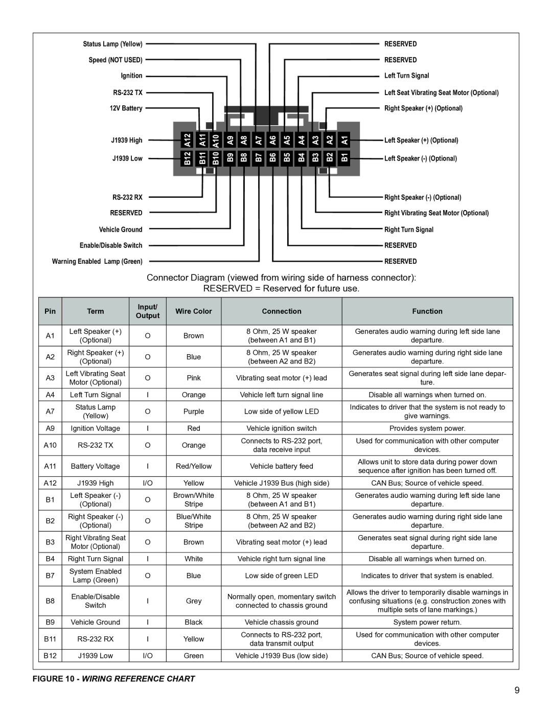
Connector Diagram (viewed from wiring side of harness connector):
RESERVED = Reserved for future use.
Pin | Term | Input/ | Wire Color | Connection | Function | |
Output | ||||||
|
|
|
|
| ||
|
|
|
|
|
| |
A1 | Left Speaker (+) | O | Brown | 8 Ohm, 25 W speaker | Generates audio warning during left side lane | |
(Optional) | (between A1 and B1) | departure. | ||||
|
|
| ||||
A2 | Right Speaker (+) | O | Blue | 8 Ohm, 25 W speaker | Generates audio warning during right side lane | |
(Optional) | (between A2 and B2) | departure. | ||||
|
|
| ||||
A3 | Left Vibrating Seat | O | Pink | Vibrating seat motor (+) lead | Generates seat signal during left side lane depar- | |
Motor (Optional) | ture. | |||||
|
|
|
| |||
A4 | Left Turn Signal | I | Orange | Vehicle left turn signal line | Disable all warnings when turned on. | |
A7 | Status Lamp | O | Purple | Low side of yellow LED | Indicates to driver that the system is not ready to | |
(Yellow) | give warnings. | |||||
|
|
|
| |||
A9 | Ignition Voltage | I | Red | Vehicle ignition switch | Provides system power. | |
A10 |
| O | Orange | Connects to | Used for communication with other computer | |
data receive input | devices. | |||||
|
|
|
| |||
A11 | Battery Voltage | I | Red/Yellow | Vehicle battery feed | Allows unit to store data during power down | |
sequence after ignition has been turned off. | ||||||
|
|
|
|
| ||
A12 | J1939 High | I/O | Yellow | Vehicle J1939 Bus (high side) | CAN Bus; Source of vehicle speed. | |
B1 | Left Speaker | O | Brown/White | 8 Ohm, 25 W speaker | Generates audio warning during left side lane | |
(Optional) | Stripe | (between A1 and B1) | departure. | |||
|
| |||||
B2 | Right Speaker | O | Blue/White | 8 Ohm, 25 W speaker | Generates audio warning during right side lane | |
(Optional) | Stripe | (between A2 and B2) | departure. | |||
|
| |||||
B3 | Right Vibrating Seat | O | Brown | Vibrating seat motor (+) lead | Generates seat signal during right side lane | |
Motor (Optional) | departure. | |||||
|
|
|
| |||
B4 | Right Turn Signal | I | White | Vehicle right turn signal line | Disable all warnings when turned on. | |
|
|
|
|
|
| |
B7 | System Enabled | O | Blue | Low side of green LED | Indicates to driver that system is enabled. | |
Lamp (Green) | ||||||
|
|
|
|
| ||
| Enable/Disable |
|
| Normally open, momentary switch | Allows the driver to temporarily disable warnings in | |
B8 | I | Grey | confusing situations (e.g. construction zones with | |||
Switch | connected to chassis ground | |||||
|
|
| multiple sets of lane markings.) | |||
|
|
|
|
| ||
B9 | Vehicle Ground | I | Black | Vehicle chassis ground | System power return. | |
|
|
|
|
|
| |
B11 | I | Yellow | Connects to | Used for communication with other computer | ||
data transmit output | devices. | |||||
|
|
|
| |||
B12 | J1939 Low | I/O | Green | Vehicle J1939 Bus (low side) | CAN Bus; Source of vehicle speed. | |
|
|
|
|
|
|
FIGURE 10 - WIRING REFERENCE CHART
9