Installation Instructions
AutoVue® Lane Departure Warning (LDW) System (3G) by Bendix CVS
PREPARATION
The vehicle must be parked on level ground. Switch off the ignition and disconnect the battery.
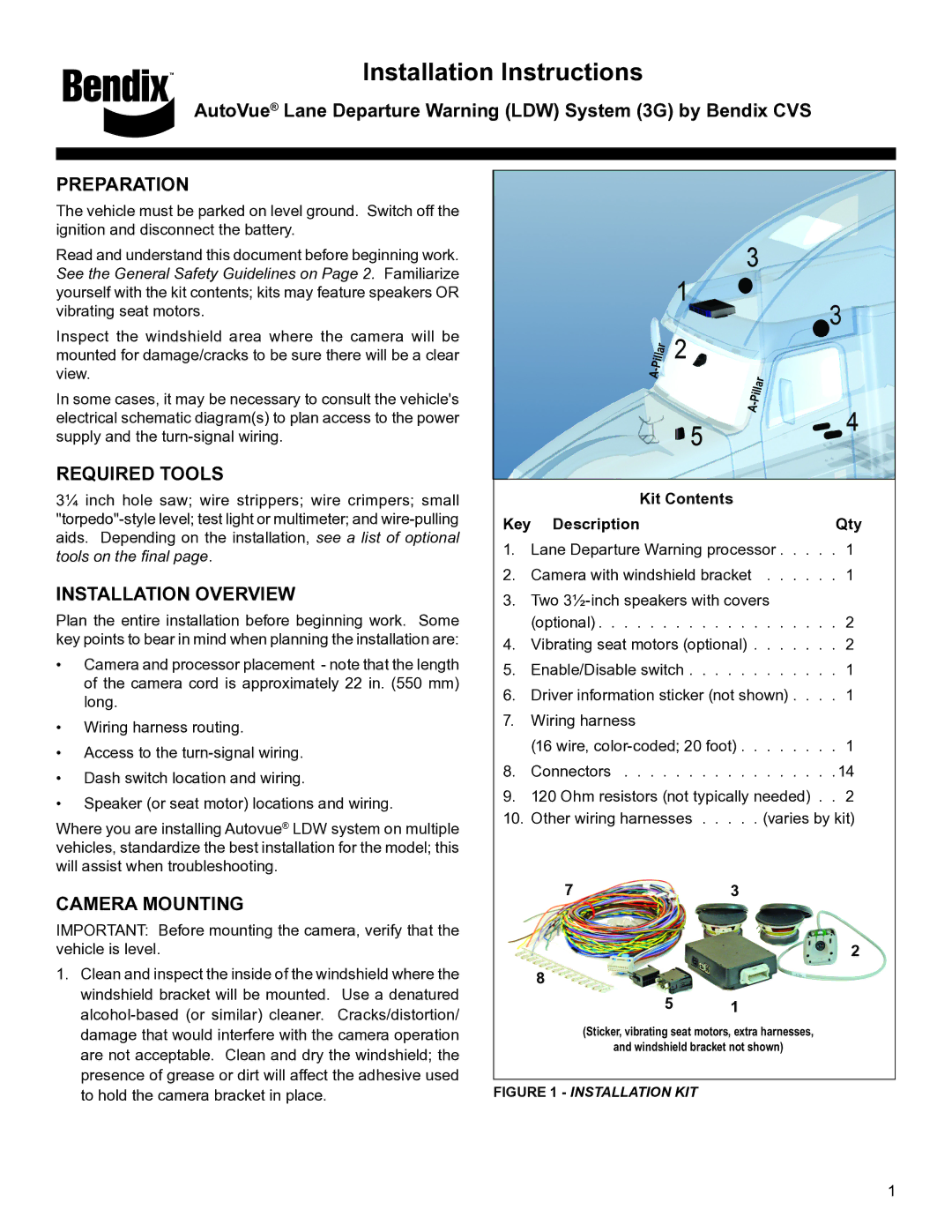
Read and understand this document before beginning work. See the General Safety Guidelines on Page 2. Familiarize yourself with the kit contents; kits may feature speakers OR vibrating seat motors.
Inspect the windshield area where the camera will be mounted for damage/cracks to be sure there will be a clear view.
In some cases, it may be necessary to consult the vehicle's electrical schematic diagram(s) to plan access to the power supply and the
REQUIRED TOOLS
3¼ inch hole saw; wire strippers; wire crimpers; small
INSTALLATION OVERVIEW
Plan the entire installation before beginning work. Some key points to bear in mind when planning the installation are:
•Camera and processor placement - note that the length of the camera cord is approximately 22 in. (550 mm) long.
•Wiring harness routing.
•Access to the
•Dash switch location and wiring.
•Speaker (or seat motor) locations and wiring.
Where you are installing Autovue® LDW system on multiple vehicles, standardize the best installation for the model; this will assist when troubleshooting.
CAMERA MOUNTING
IMPORTANT: Before mounting the camera, verify that the vehicle is level.
1.Clean and inspect the inside of the windshield where the windshield bracket will be mounted. Use a denatured
Pillar |
|
- |
|
A | Pillar |
| |
| - |
| A |
| Kit Contents |
|
Key Description | Qty | |
1. Lane Departure Warning processor | 1 | |
2. | Camera with windshield bracket . . | . . 1 |
3. | Two |
|
| (optional) | 2 |
4.Vibrating seat motors (optional) . . . . . 2
5.Enable/Disable switch . . . . . . . . 1
6. | Driver information sticker (not shown) | 1 |
7. | Wiring harness |
|
| (16 wire, | 1 |
8.Connectors . . . . . . . . . . . 14
9.120 Ohm resistors (not typically needed) . . 2
10.Other wiring harnesses . . . (varies by kit)
73
2
8
5 1
(Sticker, vibrating seat motors, extra harnesses,
and windshield bracket not shown)
FIGURE 1 - INSTALLATION KIT
1
