Right Speaker Positive - Blue
|
|
|
|
|
| Right Speaker Negative - Blue/white stripe |
| |
|
|
|
|
|
| Right Vibrating Seat Motor - Brown |
| |
Speed (Yellow/Black) Not Used |
|
|
|
| Left Vibrating Seat Motor - Pink |
| ||
|
|
|
|
|
|
| ||
| Ground - Black |
| LDW PROCESSOR |
|
| |||
RS232 | RS232 RX - Yellow |
|
|
| ||||
|
|
|
|
|
|
| ||
COMM | RS232 TX - Orange |
|
|
|
|
|
|
|
DB9 |
|
|
|
|
|
|
| |
|
|
|
|
|
|
|
| |
Left Speaker Positive - Brown |
|
|
|
|
|
|
| |
Left Speaker Negative - Brown/White Stripe |
|
|
|
|
| LDW |
| |
|
|
|
|
|
|
|
| |
|
|
|
|
|
| CAMERA |
| |
|
|
| Warning Enabled Lamp - Blue |
|
|
|
| |
|
|
|
|
|
| Ignition - Red |
| |
|
|
| 12 Volt Ignition |
|
|
|
| (A, B, and C |
|
|
| Source |
|
| 12V Battery | A B C | |
|
|
|
|
| are Contact | |||
|
|
|
| Green LED | Red/Yellow |
| Designators for | |
|
|
|
| Stripe |
| |||
|
|
|
|
| this Connector) | |||
|
|
|
| 10 | 9 | 12 Volt Battery |
| |
|
|
| Ignition - Red |
|
| |||
|
|
|
|
|
| Source |
|
|
|
| Enable/ Disable Switch - Grey | 1 |
|
|
|
| |
|
|
|
| 2 |
| Enable/ |
|
|
|
|
|
|
| Disable |
|
| |
|
|
|
|
|
|
|
| |
|
|
|
| 4 |
| Switch |
|
|
|
|
|
|
|
|
|
| |
Left Speaker |
|
|
| 12 | 11 |
|
|
|
|
| Ground - Black |
|
|
|
|
| |
| J1939 Pos |
|
| Amber LED |
|
| Right Speaker | |
| Yellow |
|
|
|
|
|
| |
J1939 CAN Bus |
|
|
|
|
|
|
| |
|
| Status Lamp Output - Purple |
|
| ||||
| J1939 Neg |
|
|
| ||||
|
|
|
|
|
|
|
| |
| Green |
| Chassis |
|
| Ignition - Red |
| |
|
|
|
|
|
| |||
|
|
|
|
|
| NOTE: This wiring | ||
|
|
| Ground |
|
|
| ||
|
|
|
|
|
| diagram shows | ||
|
|
|
|
|
|
|
| |
|
|
|
|
|
|
|
| both speaker |
|
|
|
|
|
|
|
| and vibrating |
|
|
|
|
|
| Left | Right | seat motor |
Left Turn | (Orange) | (White) | Right Turn |
|
| Seat | Seat | connections; |
Signal |
|
| Signal |
|
| Motor | Motor | actual harnesses |
|
|
|
|
|
| will have only one | ||
Positive |
|
| Positive |
|
|
|
| |
|
|
|
|
|
| or the other. | ||
|
|
|
|
|
|
|
| |
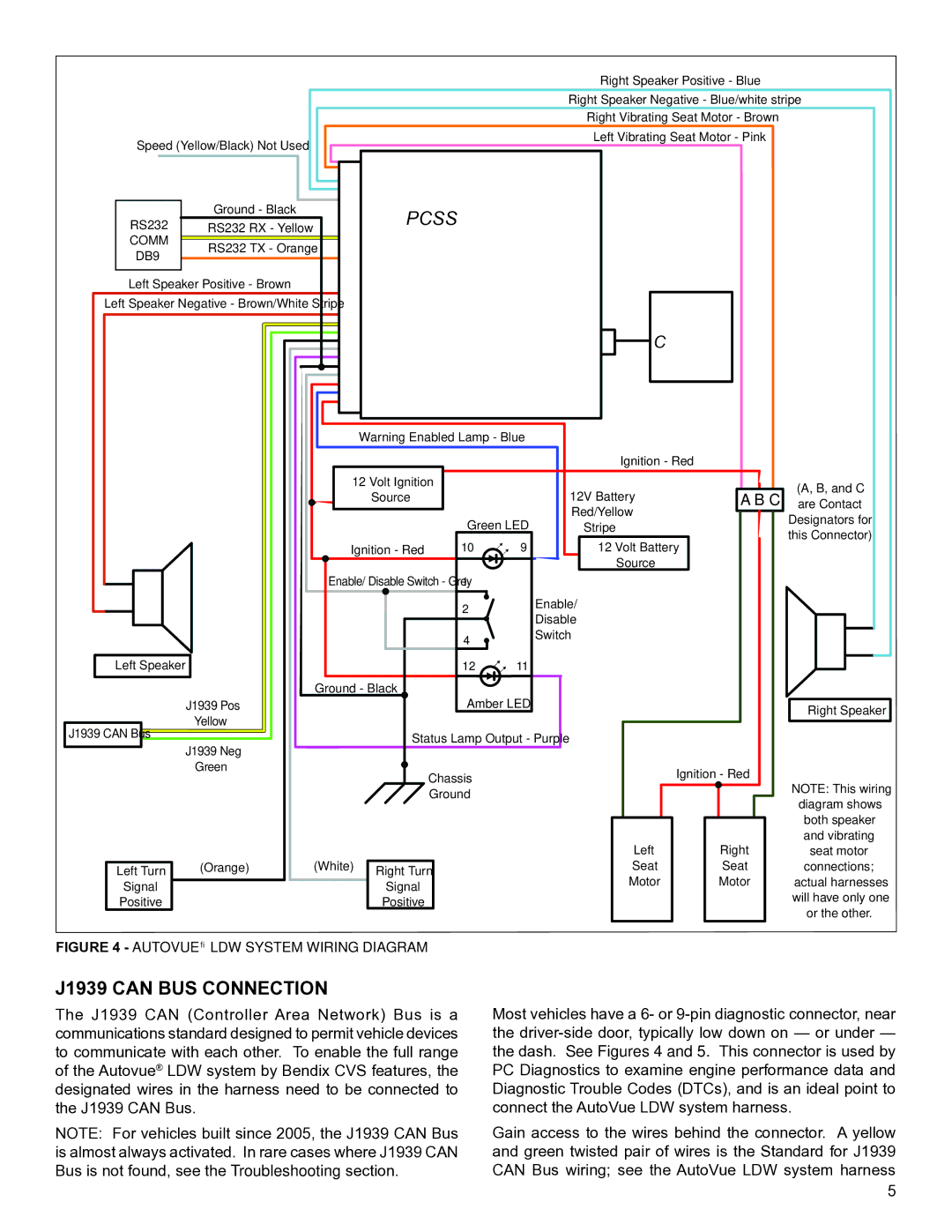
FIGURE 4 - AUTOVUE® LDW SYSTEM WIRING DIAGRAM
J1939 CAN BUS CONNECTION
The J1939 CAN (Controller Area Network) Bus is a communications standard designed to permit vehicle devices to communicate with each other. To enable the full range of the Autovue® LDW system by Bendix CVS features, the designated wires in the harness need to be connected to the J1939 CAN Bus.
NOTE: For vehicles built since 2005, the J1939 CAN Bus is almost always activated. In rare cases where J1939 CAN Bus is not found, see the Troubleshooting section.
Most vehicles have a 6- or
Gain access to the wires behind the connector. A yellow and green twisted pair of wires is the Standard for J1939 CAN Bus wiring; see the AutoVue LDW system harness
5