DESICCANT
BED
COMPRESSOROIL
COALESCING
FILTER
|
|
| CONTROL |
| PURGE |
|
|
| LINE |
| ORIFICE |
|
|
|
|
| PURGE AIR |
CONTROL |
|
| EXTENDED | ||
|
| PURGE | |||
PORT |
|
| PORT | ||
TURBO |
|
| REAR | ||
|
|
|
| RESERVOIR | |
VALVE |
|
| DELIVERY | ||
(CLOSED) |
|
| CHECK | ||
|
|
|
|
| VALVE |
SUPPLY |
|
|
| ||
PORT |
|
|
| ||
| SAFETY |
|
| FRONT | |
| VALVE | EXHAUST |
| RESERVOIR | |
|
|
| PURGE |
|
|
|
|
| VALVE |
| DELIVERY |
|
|
|
| GOVERNOR | |
|
|
| EXHAUST | PORT | |
|
|
|
|
| |
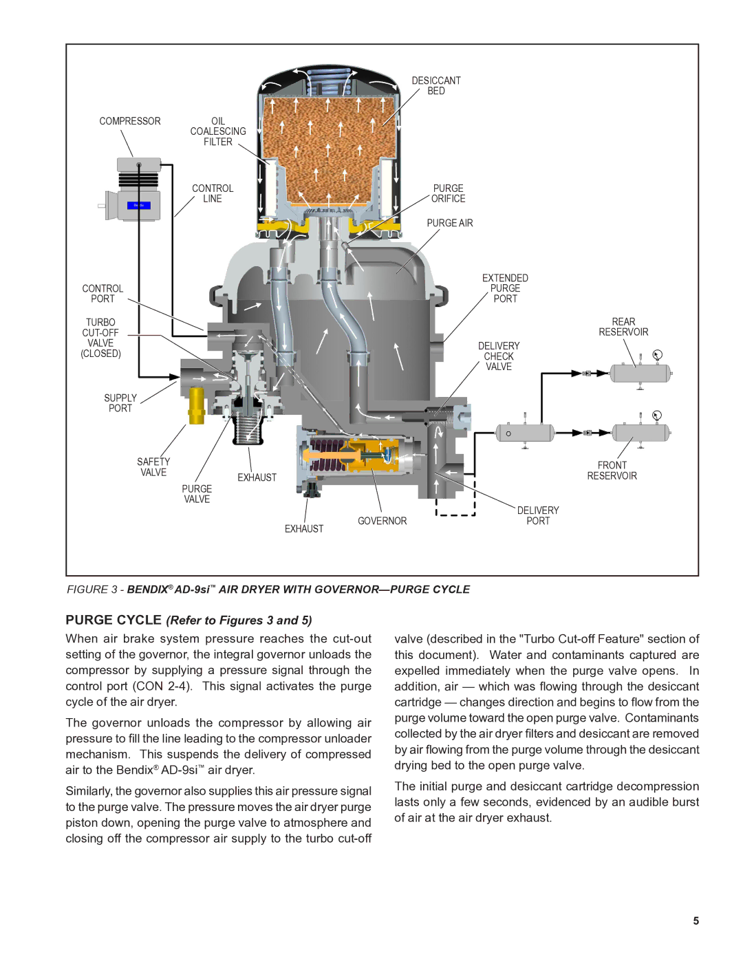
FIGURE 3 - BENDIX® AD-9si™ AIR DRYER WITH GOVERNOR—PURGE CYCLE
PURGE CYCLE (Refer to Figures 3 and 5)
When air brake system pressure reaches the
The governor unloads the compressor by allowing air pressure to fill the line leading to the compressor unloader mechanism. This suspends the delivery of compressed air to the Bendix®
Similarly, the governor also supplies this air pressure signal to the purge valve. The pressure moves the air dryer purge piston down, opening the purge valve to atmosphere and closing off the compressor air supply to the turbo
valve (described in the "Turbo
The initial purge and desiccant cartridge decompression lasts only a few seconds, evidenced by an audible burst of air at the air dryer exhaust.
5
