INSTALLATION
Step 1 — Check Jobsite — Installation, operation and maintenance instructions are provided with each unit. Before unit
IMPORTANT: This equipment is designed for indoor installation ONLY. Extreme variations in temperature, humidity and corrosive water or air will adversely affect the unit performance, reliability and service life.
The 50VS units are designed for indoor installations. Units are typically installed in a
![]() CAUTION
CAUTION
To avoid equipment damage, do not use units as a source of heating or cooling during the construction process. The mechanical components and filters used in these units quickly becomes clogged with construction dirt and debris which may cause system damage.
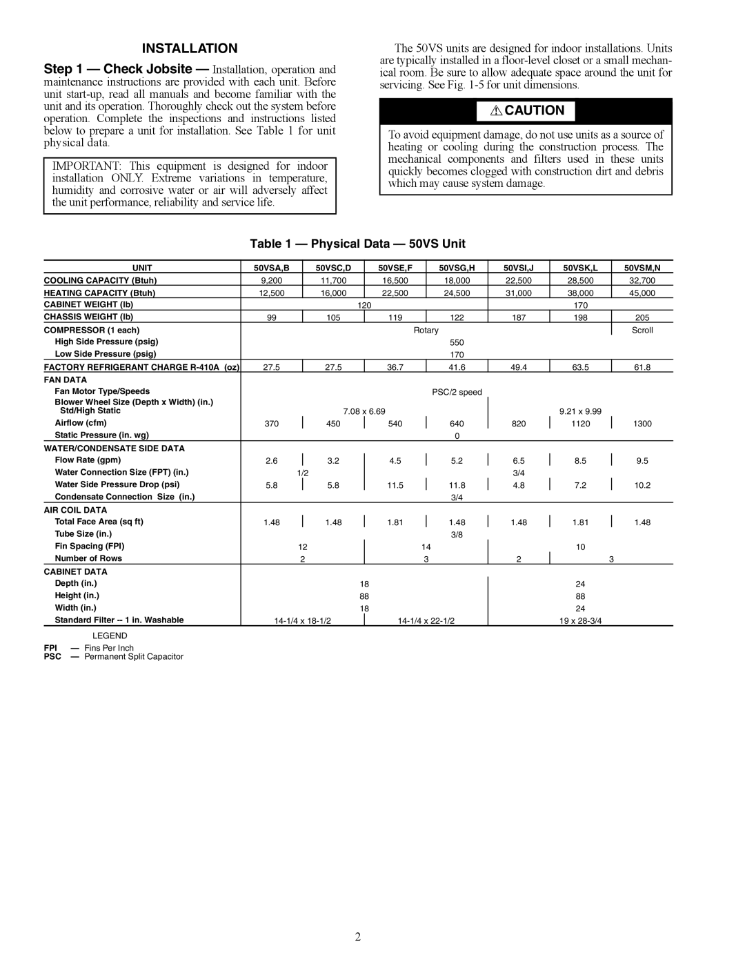
Table 1 — Physical Data — 50VS Unit
| UNIT | 50VSA,B |
| 50VSC,D |
| 50VSE,F |
| 50VSG,H | 50VSI,J | 50VSK,L |
| 50VSM,N |
COOLING CAPACITY (Btuh) | 9,200 |
| 11,700 |
| 16,500 |
| 18,000 | 22,500 | 28,500 |
| 32,700 | |
HEATING CAPACITY (Btuh) | 12,500 |
| 16,000 |
| 22,500 |
| 24,500 | 31,000 | 38,000 |
| 45,000 | |
CABINET WEIGHT (lb) |
|
|
| 120 |
|
|
| 170 |
|
| ||
CHASSIS WEIGHT (lb) | 99 |
| 105 |
| 119 |
| 122 | 187 | 198 |
| 205 | |
COMPRESSOR (1 each) |
|
|
|
|
| Rotary |
|
|
| Scroll | ||
High Side Pressure (psig) |
|
|
|
|
| 550 |
|
|
|
| ||
Low Side Pressure (psig) |
|
|
|
|
| 170 |
|
|
|
| ||
FACTORY REFRIGERANT CHARGE | 27.5 |
| 27.5 |
| 36.7 |
| 41.6 | 49.4 | 63.5 |
| 61.8 | |
FAN DATA |
|
|
|
|
|
|
|
|
|
|
| |
Fan Motor Type/Speeds |
|
|
|
|
|
| PSC/2 speed |
|
|
|
| |
Blower Wheel Size (Depth x Width) (in.) |
|
|
|
|
|
|
|
|
|
|
| |
Std/High Static |
|
| 7.08 x 6.69 |
|
|
| 9.21 x 9.99 |
|
| |||
Airflow (cfm) | 370 |
| 450 |
| 540 |
| 640 | 820 | 1120 |
| 1300 | |
Static Pressure (in. wg) |
|
|
|
|
| 0 |
|
|
|
| ||
WATER/CONDENSATE SIDE DATA |
|
|
|
|
|
|
|
|
|
|
| |
Flow Rate (gpm) | 2.6 |
| 3.2 |
| 4.5 |
| 5.2 | 6.5 | 8.5 |
| 9.5 | |
Water Connection Size (FPT) (in.) |
| 1/2 |
|
|
|
| 3/4 |
|
|
| ||
Water Side Pressure Drop (psi) | 5.8 |
| 5.8 |
| 11.5 |
| 11.8 | 4.8 | 7.2 |
| 10.2 | |
Condensate Connection Size (in.) |
|
|
|
|
| 3/4 |
|
|
|
| ||
AIR COIL DATA |
|
|
|
|
|
|
|
|
|
|
| |
Total Face Area (sq ft) | 1.48 |
| 1.48 |
| 1.81 |
| 1.48 | 1.48 | 1.81 |
| 1.48 | |
Tube Size (in.) |
|
|
|
|
| 3/8 |
|
|
|
| ||
Fin Spacing (FPI) |
| 12 |
|
| 14 |
| 10 |
|
| |||
Number of Rows |
| 2 |
|
| 3 | 2 |
| 3 | ||||
CABINET DATA |
|
|
|
|
|
|
|
|
|
|
| |
Depth (in.) |
|
|
| 18 |
|
|
| 24 |
|
| ||
Height (in.) |
|
|
| 88 |
|
|
| 88 |
|
| ||
Width (in.) |
|
|
| 18 |
|
|
| 24 |
|
| ||
Standard Filter |
|
| 19 x |
|
| |||||||
| LEGEND |
|
|
|
|
|
|
|
|
|
|
|
FPI | — Fins Per Inch |
|
|
|
|
|
|
|
|
|
|
|
PSC | — Permanent Split Capacitor |
|
|
|
|
|
|
|
|
|
|
|
2