Step 12 — Install Supply Grille
Refer to Fig. 2, 3, and 12 to determine grille size and location based on the type and size of the unit cabinet/chassis combina- tion. Perform the following to install supply grilles over the cabinet discharge openings.
1.To prevent supply air from short circuiting back into the return air panel a supply duct extension(s) is provided with each cabinet.
2.Insert the grille into the cabinet supply duct extension(s). Assure that the grille flange rests against the drywall cov- ering the cabinet.
3.Secure the grille to the drywall with the screws provided.
NO SUPPLY OPENINGS
NA |
|
|
| NC |
| NB |
|
|
|
| |||
|
|
|
|
|
|
|
SINGLE SUPPLY
| SC |
| SA |
| SB |
|
|
|
|
| |||
|
|
|
|
|
|
|
a50-8302.eps
| SG |
|
|
| SE |
|
|
| SF |
|
|
| |
|
|
|
|
|
|
|
|
|
| ||||
|
|
|
|
|
|
|
|
|
|
|
|
|
|
|
|
|
|
|
|
|
|
|
|
|
|
|
|
PRE-START-UP
Check the following before system
1.Balancing/shutoff valves: Ensure that all isolation valves are open and water control valves are wired.
2.Line voltage and wiring: Verify that voltage is within an acceptable range for the unit and wiring and fuses/break- ers are properly sized. Verify that low voltage wiring is complete.
3.Entering water and air: Ensure that entering water and air temperatures are within operating limits of Table 9.
DOUBLE SUPPLY
DB | DC | DA |
DF | DG | DE |
|
|
| DK |
|
|
|
| DL |
|
|
|
| DJ |
| ||
|
|
|
|
|
|
|
|
|
|
|
| |||||
|
|
|
|
|
|
|
|
|
|
|
| |||||
|
|
|
|
|
|
|
|
|
|
|
|
|
|
|
|
|
|
|
|
|
|
|
|
|
|
|
|
|
|
|
|
|
|
TRIPLE SUPPLY
|
|
| SL |
|
|
| SJ |
|
|
| SK |
| |
|
|
|
|
|
|
|
|
|
| ||||
|
|
|
|
|
|
|
|
|
| ||||
|
|
|
|
|
|
|
|
|
|
|
|
|
|
|
|
|
|
|
|
|
|
|
|
|
|
|
|
SUPPLY RETURN
DRAIN
RISERS
LEFT | RIGHT |
CABINET
FRONT
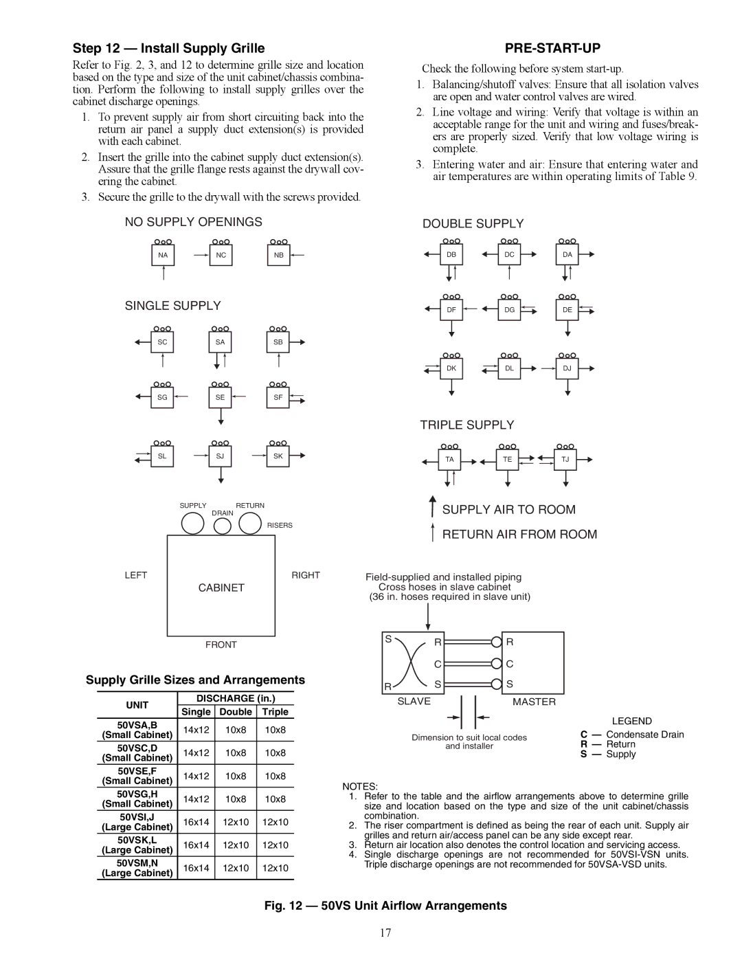
Supply Grille Sizes and Arrangements
UNIT | DISCHARGE (in.) | |||
Single | Double | Triple | ||
| ||||
50VSA,B | 14x12 | 10x8 | 10x8 | |
(Small Cabinet) | ||||
50VSC,D | 14x12 | 10x8 | 10x8 | |
(Small Cabinet) | ||||
50VSE,F | 14x12 | 10x8 | 10x8 | |
(Small Cabinet) | ||||
50VSG,H | 14x12 | 10x8 | 10x8 | |
(Small Cabinet) | ||||
50VSI,J | 16x14 | 12x10 | 12x10 | |
(Large Cabinet) | ||||
50VSK,L | 16x14 | 12x10 | 12x10 | |
(Large Cabinet) | ||||
50VSM,N | 16x14 | 12x10 | 12x10 | |
(Large Cabinet) | ||||
| TA |
|
|
| TE |
|
|
|
|
|
|
| TJ |
| ||||
|
|
|
|
|
|
|
|
|
|
|
| |||||||
|
|
|
|
|
|
|
|
|
|
|
|
|
|
|
|
|
|
|
|
|
|
|
|
|
|
|
|
|
|
|
|
|
|
|
|
|
|
|
|
|
|
|
|
|
|
|
|
|
|
|
|
|
|
|
|
|
SUPPLY AIR TO ROOM
RETURN AIR FROM ROOM
(36 in. hoses required in slave unit)
SR ![]() R
R
C ![]() C
C
RS ![]() S
S
SLAVE |
|
|
|
|
|
| MASTER |
|
|
|
|
|
|
|
|
| LEGEND |
|
|
|
|
|
|
|
| |
Dimension to suit local codes | C — Condensate Drain | |||||||
| and installer | R — Return | ||||||
S — Supply
NOTES:
1.Refer to the table and the airflow arrangements above to determine grille size and location based on the type and size of the unit cabinet/chassis combination.
2.The riser compartment is defined as being the rear of each unit. Supply air grilles and return air/access panel can be any side except rear.
3.Return air location also denotes the control location and servicing access.
4.Single discharge openings are not recommended for
Fig. 12 — 50VS Unit Airflow Arrangements
17