has reached acceptable levels, the unit microprocessor will power on automatically and resume previous operation.
LEAVING WATER TEMPERATURE SENSOR FAIL- URE (LWT) — If the leaving water temperature thermistor fails, it will not affect the operation of the unit. This sensor is for monitoring purposes only.
DISCHARGE AIR TEMPERATURE SENSOR FAILURE (DAT) — If the discharge temperature thermistor fails, it will not affect the operation of the unit. This sensor is for monitor- ing purposes only.
FREEZE PROTECTION 1 TEMPERATURE SENSOR FAILURE (FP1) — If the freeze protection 1 thermistor fails for 30 continuous seconds an FP1 lockout will occur. The
compressor will then be deenergized and the blower will deen- ergize 15 seconds after the compressor is deenergized. The sen- sor must be replaced if this lockout occurs.
FREEZE PROTECTION 2 TEMPERATURE SENSOR FAILURE (FP2) — If the freeze protection 2 thermistor fails for 30 continuous seconds an FP2 lockout will occur. The compressor will then be deenergized and the blower will deen- ergize 15 seconds after the compressor is deenergized. The sen- sor must be replaced if this lockout occurs.
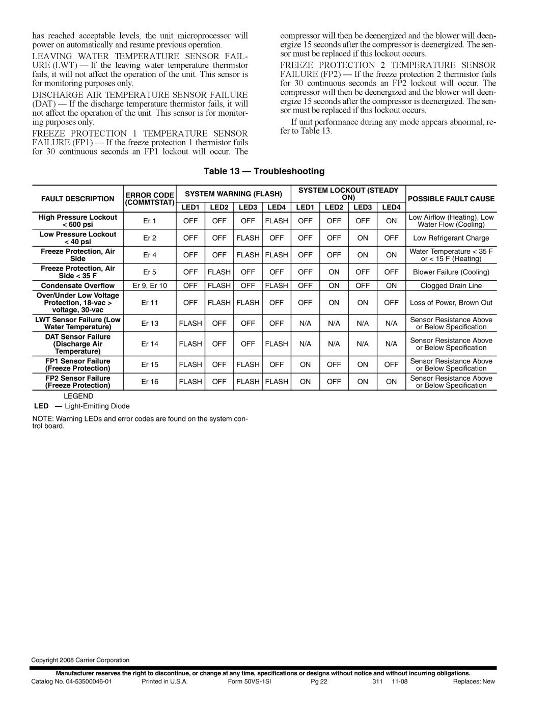
If unit performance during any mode appears abnormal, re- fer to Table 13.
Table 13 — Troubleshooting
| ERROR CODE | SYSTEM WARNING (FLASH) | SYSTEM LOCKOUT (STEADY |
| |||||||
FAULT DESCRIPTION |
| ON) |
| POSSIBLE FAULT CAUSE | |||||||
(COMMTSTAT) |
|
|
|
|
|
| |||||
| LED1 | LED2 | LED3 | LED4 | LED1 | LED2 | LED3 | LED4 |
| ||
High Pressure Lockout | Er 1 | OFF | OFF | OFF | FLASH | OFF | OFF | OFF | ON | Low Airflow (Heating), Low | |
< 600 psi | Water Flow (Cooling) | ||||||||||
|
|
|
|
|
|
|
|
| |||
Low Pressure Lockout | Er 2 | OFF | OFF | FLASH | OFF | OFF | OFF | ON | OFF | Low Refrigerant Charge | |
< 40 psi | |||||||||||
|
|
|
|
|
|
|
|
|
| ||
Freeze Protection, Air | Er 4 | OFF | OFF | FLASH | FLASH | OFF | OFF | ON | ON | Water Temperature < 35 F | |
Side | or < 15 F (Heating) | ||||||||||
|
|
|
|
|
|
|
|
| |||
Freeze Protection, Air | Er 5 | OFF | FLASH | OFF | OFF | OFF | ON | OFF | OFF | Blower Failure (Cooling) | |
Side < 35 F | |||||||||||
|
|
|
|
|
|
|
|
|
| ||
Condensate Overflow | Er 9, Er 10 | OFF | FLASH | OFF | FLASH | OFF | ON | OFF | ON | Clogged Drain Line | |
Over/Under Low Voltage |
|
|
|
|
|
|
|
|
|
| |
Protection, | Er 11 | OFF | FLASH | FLASH | OFF | OFF | ON | ON | OFF | Loss of Power, Brown Out | |
voltage, |
|
|
|
|
|
|
|
|
|
| |
LWT Sensor Failure (Low | Er 13 | FLASH | OFF | OFF | OFF | N/A | N/A | N/A | N/A | Sensor Resistance Above | |
Water Temperature) | or Below Specification | ||||||||||
|
|
|
|
|
|
|
|
| |||
DAT Sensor Failure |
|
|
|
|
|
|
|
|
| Sensor Resistance Above | |
(Discharge Air | Er 14 | FLASH | OFF | OFF | FLASH | N/A | N/A | N/A | N/A | ||
or Below Specification | |||||||||||
Temperature) |
|
|
|
|
|
|
|
|
| ||
|
|
|
|
|
|
|
|
|
| ||
FP1 Sensor Failure | Er 15 | FLASH | OFF | FLASH | OFF | ON | OFF | ON | OFF | Sensor Resistance Above | |
(Freeze Protection) | or Below Specification | ||||||||||
|
|
|
|
|
|
|
|
| |||
FP2 Sensor Failure | Er 16 | FLASH | OFF | FLASH | FLASH | ON | OFF | ON | ON | Sensor Resistance Above | |
(Freeze Protection) | or Below Specification | ||||||||||
|
|
|
|
|
|
|
|
| |||
LEGEND
LED — Light-Emitting Diode
NOTE: Warning LEDs and error codes are found on the system con- trol board.
Copyright 2008 Carrier Corporation
Manufacturer reserves the right to discontinue, or change at any time, specifications or designs without notice and without incurring obligations.
Catalog No. | Printed in U.S.A. | Form | Pg 22 | 311 | Replaces: New |