6.When all units on a riser are anchored into place, com- plete riser joints as follows:
a.Verify that all riser joints are vertically aligned and that risers penetrate at least 1 in. into the swaged joint of the riser below. DO NOT let riser joint bot- tom out.
b.Braze riser joints with a
c.Anchor
d.Verify that unit
e.Flush system; refer to System Cleaning and Flush- ing section for more information.
f.Install vents in piping loop as required to bleed the system of air accumulated during installation.
7.Install supply duct extension(s) provided with the cabinet by folding the tabs down to secure extension(s) to cabinet.
COMMERCIAL WATER LOOP APPLICATION — Com- mercial systems typically include a number of units connected to a common piping system. Any unit plumbing maintenance work can introduce air into the piping system; therefore, air elimination equipment is a major portion of the mechanical room plumbing. In piping systems expected to utilize water temperatures below 50 F, 1/2 in.
Teflon tape thread sealant is recommended for use in system piping to minimize internal fouling of the heat exchanger. Do not over tighten connections and route piping so as not to inter- fere with service or maintenance access. Hose kits include shut off valves, pressure/temperature (P/T) plugs for performance measurement, high pressure stainless steel braided hose, and hose adaptors.
Balancing valves and variable speed pumping systems my also be used.
The piping system should be flushed to remove dirt, pipe shavings, chips, and other foreign material prior to operation. See System Cleaning and Flushing section. The flow rate is usually set between 2.25 and 3.5 gpm per ton for most applications of water loop heat pumps. To ensure proper main- tenance and servicing, P/T ports are imperative for temperature and flow verification, as well as performance checks.
Water loop heat pump (cooling tower/boiler) systems typi- cally utilize a common loop, maintained between 60 to 90 F. The use of a closed circuit evaporate cooling tower with a sec- ondary heat exchanger between the tower and the water loop is recommended. If an open type cooling tower is used continu- ously, chemical treatment and filtering will be necessary.
NOTE: In most commercial building applications using a frame style or plate style
Piping Installation — All earth loop piping materials should be limited to polyethylene fusion only for in ground sections of the loop. Galvanized or steel fittings should not be used at any time due to their tendency to corrode. All plastic to metal threaded fittings should be avoided due to their potential to leak in earth coupled applications. A flanged fitting should be sub- stituted. P/T plugs should be used so that flow can be measured using the pressure drop of the unit heat exchanger.
Earth loop temperatures can range between 25 and 110 F. Flow rates between 2.25 and 3.0 gpm per ton of cooling capac- ity is recommended in these applications.
Test individual horizontal loop circuits before backfilling. Test vertical
Pressures of at least 100 psi should be used when testing. Do not exceed the pipe pressure rating. Test entire system when all loops are assembled.
Flushing the Earth Loop — Upon completion of system in- stallation and testing, flush the system to remove all foreign ob- jects and purge to remove all air.
Antifreeze — In areas when minimum entering loop tempera- tures drop below 40 F or where piping will be routed through areas subject to freezing, antifreeze is required. Alcohols and glycols are commonly used as antifreeze; however your local Carrier distributor should be consulted for the antifreeze best suited to your area. Freeze protection should be maintained to 15 F below the lowest expected entering loop temperature. For example, if 30 F is the minimum expected entering loop tem- perature, the leaving loop temperature would be 25 to 22 F and freeze protection should be at 15 F. Calculation as follows:
30 F – 15 F = 15 F.
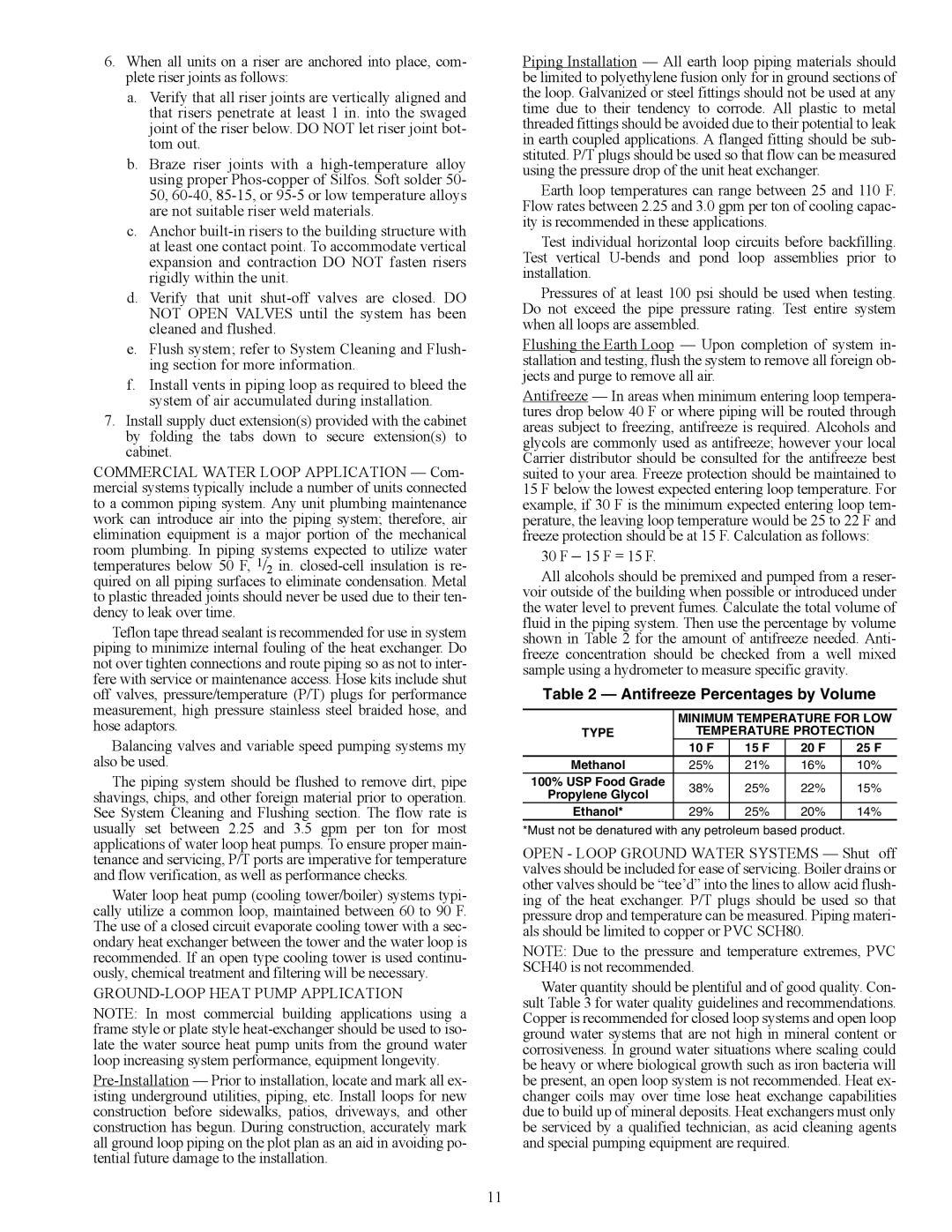
All alcohols should be premixed and pumped from a reser- voir outside of the building when possible or introduced under the water level to prevent fumes. Calculate the total volume of fluid in the piping system. Then use the percentage by volume shown in Table 2 for the amount of antifreeze needed. Anti- freeze concentration should be checked from a well mixed sample using a hydrometer to measure specific gravity.
Table 2 — Antifreeze Percentages by Volume
| MINIMUM TEMPERATURE FOR LOW | ||||
TYPE | TEMPERATURE PROTECTION | ||||
| 10 F | 15 F | 20 F | 25 F | |
Methanol | 25% | 21% | 16% | 10% | |
100% USP Food Grade | 38% | 25% | 22% | 15% | |
Propylene Glycol | |||||
|
|
|
| ||
Ethanol* | 29% | 25% | 20% | 14% | |
*Must not be denatured with any petroleum based product.
OPEN - LOOP GROUND WATER SYSTEMS — Shut off valves should be included for ease of servicing. Boiler drains or other valves should be “tee’d” into the lines to allow acid flush- ing of the heat exchanger. P/T plugs should be used so that pressure drop and temperature can be measured. Piping materi- als should be limited to copper or PVC SCH80.
NOTE: Due to the pressure and temperature extremes, PVC SCH40 is not recommended.
Water quantity should be plentiful and of good quality. Con- sult Table 3 for water quality guidelines and recommendations. Copper is recommended for closed loop systems and open loop ground water systems that are not high in mineral content or corrosiveness. In ground water situations where scaling could be heavy or where biological growth such as iron bacteria will be present, an open loop system is not recommended. Heat ex- changer coils may over time lose heat exchange capabilities due to build up of mineral deposits. Heat exchangers must only be serviced by a qualified technician, as acid cleaning agents and special pumping equipment are required.
11