DIGITAL
VOLT/
POWEROHM
SUPPLY METER (9-16 VDC)
| PIN C |
RESISTOR | GROUND |
| |
TEST LOAD | PIN B |
(47,000 OHM FOR | |
DETROIT DIESEL, | VOUT |
300,000 OHM | (OUTPUT) |
FOR MACK) | PIN A |
| |
| VREF |
| (INPUT) |
| POTENTIOMETER |
| POTENTIOMETER |
| PC. NO. ON THIS |
| SURFACE |
FIGURE 5 - ET-2™ TREADLE ELECTRICAL TEST
SCHEMATIC FOR THE DETROIT DIESEL CONNECTOR
wear, or physical damage. Check
2.Remove the
3.Secure the
4.Connect the potentiometer to the volt meter and power supply as shown in Figure 5. NOTE: Power supply can be a 12 VDC vehicle battery in good condition and with known voltage output.
5.Verify that the closed throttle (idle) output voltage, as a percentage of supply voltage, is within the limits listed in Figure 2.
6.Depress the treadle to its full throttle position. The output voltage, as a percentage of supply voltage, should be within the limits listed in Figure 2, e.g. Testing a Detroit Diesel
7.Make several full applications and record idle position voltage each time. Verify that idle position voltage does not vary by more than .4% (.02 volts). If the
A B C
PACKARD ELECTRIC CONNECTOR 12010717 (CONNECTOR X)
INPUT PIN 3
OUTPUT PIN 2
GROUND PIN 1
| PACKARD ELECTRIC |
| CONNECTOR 12015793 |
C B A | (CONNECTOR Y) |
|
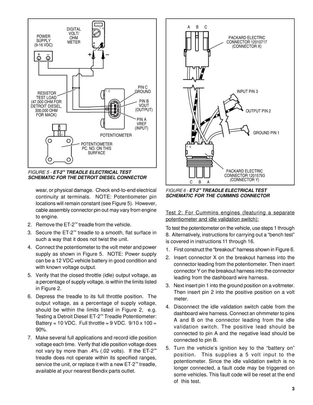
FIGURE 6 - ET-2™ TREADLE ELECTRICAL TEST
SCHEMATIC FOR THE CUMMINS CONNECTOR
Test 2: For Cummins engines (featuring a separate potentiometer and idle validation switch):
To test the potentiometer on the vehicle, use steps 1 through
8.Alternatively, instructions for carrying out a “bench test” is covered in instructions 11 through 16.
1.First construct the “breakout” harness shown in Figure 6.
2.Insert connector X on the breakout harness into the connector leading from the potentiometer. Then insert connector Y on the breakout harness into the connector leading from the dashboard wire harness.
3.Next insert pin 1 into the ground position on a voltmeter. Then insert pin 2 into the positive position on a volt meter.
4.Disconnect the idle validation switch cable from the dashboard wire harness. Connect an ohmmeter to pins A and B on the connector leading from the idle validation switch. The positive lead should be connected to pin A and the negative lead should be connected to pin B.
5.Turn the vehicle’s ignition key to the “battery on” position. This supplies a 5 volt input to the potentiometer. Since the idle validation switch is no longer connected, a fault code may be triggered on some vehicles. This fault code will be reset at the end of this test.
3