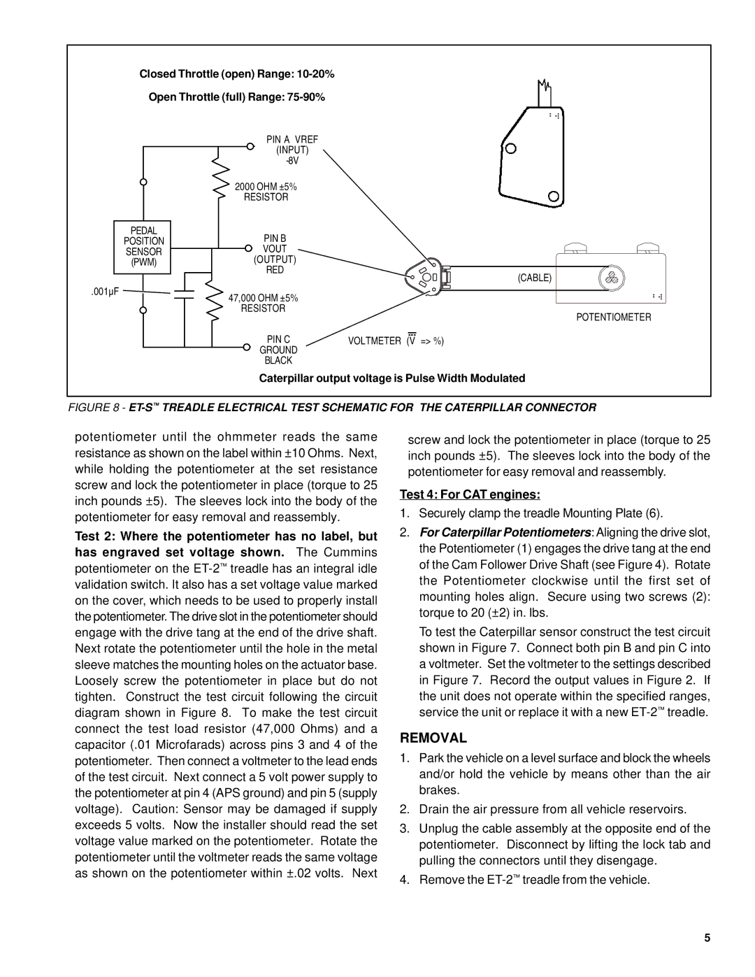
Closed Throttle (open) Range:
Open Throttle (full) Range:
| PIN A VREF |
|
| (INPUT) |
|
|
| |
| 2000 OHM ±5% |
|
| RESISTOR |
|
PEDAL | PIN B |
|
POSITION |
| |
SENSOR | VOUT |
|
(PWM) | (OUTPUT) |
|
| RED | (CABLE) |
|
| |
.001µF | 47,000 OHM ±5% |
|
|
| |
| RESISTOR | POTENTIOMETER |
|
| |
| PIN C | VOLTMETER (V => %) |
| GROUND |
|
| BLACK |
|
Caterpillar output voltage is Pulse Width Modulated
FIGURE 8 - ET-S™ TREADLE ELECTRICAL TEST SCHEMATIC FOR THE CATERPILLAR CONNECTOR
potentiometer until the ohmmeter reads the same resistance as shown on the label within ±10 Ohms. Next, while holding the potentiometer at the set resistance screw and lock the potentiometer in place (torque to 25 inch pounds ±5). The sleeves lock into the body of the potentiometer for easy removal and reassembly.
Test 2: Where the potentiometer has no label, but
has engraved set voltage shown. The Cummins potentiometer on the
screw and lock the potentiometer in place (torque to 25 inch pounds ±5). The sleeves lock into the body of the potentiometer for easy removal and reassembly.
Test 4: For CAT engines:
1.Securely clamp the treadle Mounting Plate (6).
2.For Caterpillar Potentiometers: Aligning the drive slot, the Potentiometer (1) engages the drive tang at the end of the Cam Follower Drive Shaft (see Figure 4). Rotate the Potentiometer clockwise until the first set of mounting holes align. Secure using two screws (2): torque to 20 (±2) in. lbs.
To test the Caterpillar sensor construct the test circuit shown in Figure 7. Connect both pin B and pin C into a voltmeter. Set the voltmeter to the settings described in Figure 7. Record the output values in Figure 2. If the unit does not operate within the specified ranges, service the unit or replace it with a new
REMOVAL
1.Park the vehicle on a level surface and block the wheels and/or hold the vehicle by means other than the air brakes.
2.Drain the air pressure from all vehicle reservoirs.
3.Unplug the cable assembly at the opposite end of the potentiometer. Disconnect by lifting the lock tab and pulling the connectors until they disengage.
4.Remove the
5