Manuals
/
Bertazzoni
/
Kitchen Appliance
/
Range
Bertazzoni
A304GGVXE, A304GGVXT
dimensions
Models:
A304GGVXT
A304GGVXE
1
42
44
44
Download
44 pages
34.06 Kb
37
38
39
40
41
42
43
44
Specification
Install
Parts list
Wiring Diagram
Symbols
Warranty
Minimum Flame Adjustment
Cleaning Your Range
Safety
Tips for Using Pans Correctly
Page 42
Image 42
Page 41
Page 43
Page 42
Image 42
Page 41
Page 43
Contents
INSTALLATION, USE & Care Manual Freestanding GAS Ranges
From the desk of the President
Table of Contents
Warranty and Service
Customer Service
Replacement Parts
Important Safety Information
What to do if YOU Smell GAS
Product Specifications
Auxiliary 3400 BTU/h
Before Installation
Type of GAS
Installing the Legs
Installing the HOB Rail and Oven Handle
Only model A304GGVXT
Installing the Worktop Frontguard
Only model A304GGVXE
Installing the Backguard
Device
Electrical
GAS
Installation Adjacent to Kitchen Cabinets
Exhaust Hood Installation
Electrical Grounding
Wiring Diagram
Electrical Connection
Electrical Shock Hazard
Manual SHUT‐OFF Valve
Do not USE AN Open Flame When Checking For Leaks
GAS Connection
Flexible Connections
Pressure Regulator
GAS Conversion
Surface Burners
Main Oven Burner
To replace the nozzles of the main oven burner, start by
Broiler Burner
Visual Checks
Connection of Thermocouples to Thermostat
Minimum Flame Adjustment
Oven Burner
Models
Burner
Installation CHECKLlST
Final Preparation
Surface Burner Layout
Room Ventilation
Symbols
Surface Cooking
Surface Burner Operation
Tips for Using Pans Correctly
Oven Cooking
Oven on/off
GAS Oven Operation Thermocouple Safety Valve
Oven Shelves
Electric Ignition
Convection Cooking
Using the Thermometer
Always keep the oven door open when lighting Gas broiler
Cooking with the GAS Broiler
Replacing the Oven Light Bulb
Cleaning Your Range
Maintaining Your Range
Cooling FAN Failure
Important Appliance Information
Italy
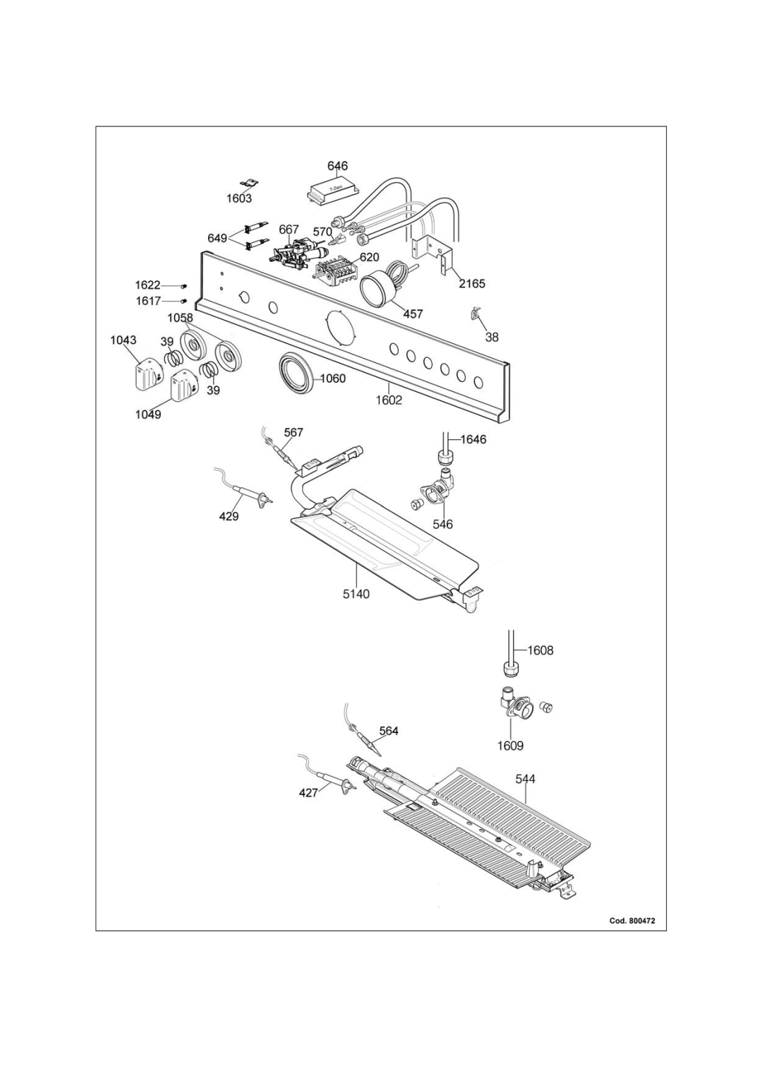
Spare Parts List
Dual Burner
Page
Page
Page
Page
M7S0GNA4X5AUA A304GGVXT GAS Cooker
Thermometer Knob Ring
Page
Page
Top
Page
Image
Contents