INSTALLING THE ANTI‐TIP STABILlTY
DEVICE
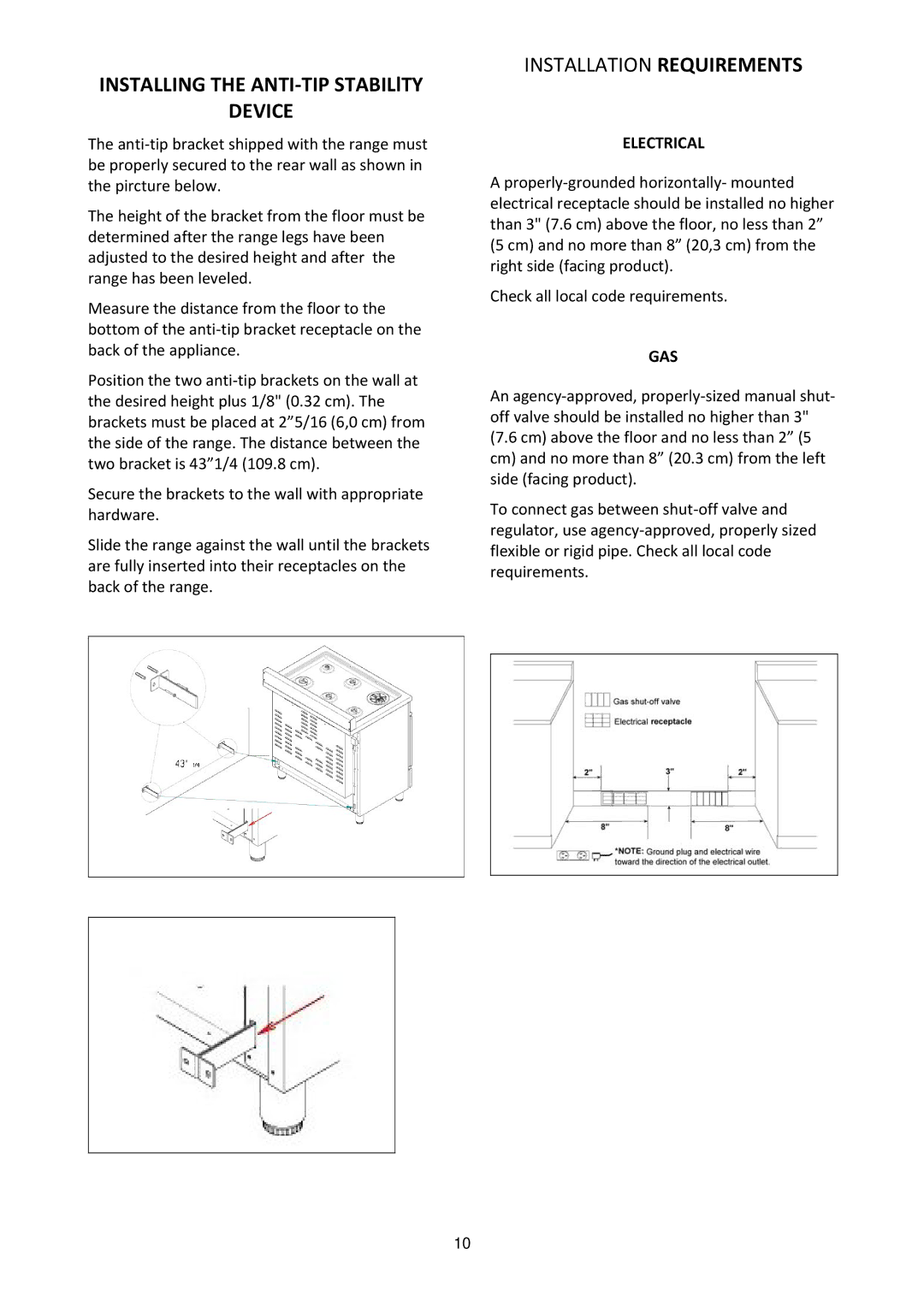
The anti‐tip bracket shipped with the range must be properly secured to the rear wall as shown in the pircture below.
The height of the bracket from the floor must be determined after the range legs have been adjusted to the desired height and after the range has been leveled.
Measure the distance from the floor to the bottom of the anti‐tip bracket receptacle on the back of the appliance.
Position the two anti‐tip brackets on the wall at the desired height plus 1/8" (0.32 cm). The brackets must be placed at 2”5/16 (6,0 cm) from the side of the range. The distance between the two bracket is 43”1/4 (109.8 cm).
Secure the brackets to the wall with appropriate hardware.
Slide the range against the wall until the brackets are fully inserted into their receptacles on the back of the range.
INSTALLATION REQUIREMENTS
ELECTRICAL
Aproperly‐grounded horizontally‐ mounted electrical receptacle should be installed no higher than 3" (7.6 cm) above the floor, no less than 2” (5 cm) and no more than 8” (20,3 cm) from the right side (facing product).
Check all local code requirements.
GAS
An agency‐approved, properly‐sized manual shut‐ off valve should be installed no higher than 3" (7.6 cm) above the floor and no less than 2” (5 cm) and no more than 8” (20.3 cm) from the left side (facing product).
To connect gas between shut‐off valve and regulator, use agency‐approved, properly sized flexible or rigid pipe. Check all local code requirements.
10
