Manuals
/
Billion Electric Company
/
Computer Equipment
/
Network Router
Billion Electric Company
8501
user manual
Configuration, LAN Local Area Network, Bridge Interface
Models:
8501
1
31
134
134
Download
134 pages
2.47 Kb
28
29
30
31
32
33
34
35
Troubleshooting
Install
Connection Diagram
Error Log
Connecting Your Router
Configuring PCs in Windows
Problem
Diagnostic
Remote Access
Setup Member Ports
Page 31
Image 31
Page 30
Page 32
Page 31
Image 31
Page 30
Page 32
Contents
Version Release
BiPAC 8500/8501/8520
SHDSL VPN Firewall Bridge Router
User’s Manual
Table of Contents
Advanced
QoS Quality of Service
CHAPTER 5 TROUBLESHOOTING
Time Schedule
Fast Ethernet Switch
Features
Chapter 1 Introduction
Introduction to your Router
Virtual Private Network VPN
Dynamic Host Configuration Protocol DHCP client and server
Domain Name System DNS relay
Dynamic Domain Name System DDNS
Rich Management Interfaces
Firmware Upgradeable
Do not use the same power source for this router as other equipment
Chapter 2 Installing the Router
Important note for using this router
Package Contents
RJ-45 connector
The Front LEDs of BiPAC
Lit when power is ON
Lit when the system is ready
LED LINE 1 LAN Port
1X - 4X RJ-45 connector
SYS PWR
LINE
LED PWR SYS LAN Port
*Only the BiPAC 8520 has two Line jack ports. BiPAC 8500 has one
The Rear Ports of BiPAC 8500
Port 1 Power Switch 2 PWR 3 RESET LAN 4 1X
5 CONSOLE LINE 6 1X - 2X RJ-11 connector
5 CONSOLE 6 LINE
The Rear Ports of BiPAC
Cabling
Port 1 Power Switch 2 PWR 3 RESET LAN 4 1X - 4X RJ-45 connector
Connecting Your Router
Chapter 3 Basic Installation
2. Double-click Local Area Connection. See Figure
Configuring PCs in Windows in Window XP
4. Select Internet Protocol TCP/IP and click Properties. See Figure
2. Double-click Local Area “LAN” Connection. See Figure
Configuring PCs in Windows
4. Select Internet Protocol TCP/IP and click Properties See Figure
5. Then select the DNS Configuration tab. See Figure
Configuring PC in Windows 95/98/ME
3. Click Properties
2. Select TCP/IP Protocol and click Properties. See Figure
Configuring PC in Windows NT4.0
ISP setting in WAN site
Factory Default Settings
Web Interface Username and Password
Device LAN IP settings
PPPoE PPPoE / PPPoE with Pass-through PPPoA RFC 1483 Bridged
Information from your ISP
RFC 1483 Routed IPoA Routed IP over ATM
Congratulation! You are now successfully logon to the SHDSL Router
Configuring with your Web Browser
Status
Chapter 4 Configuration
Quick Start Configuration
Save Config to FLASH
Routing Table
Status
ARP Table
Routing Table
Expired Table
DHCP Table
PPTP Status
Leased Table
IPSec Status
Email Status
L2TP Status
Event Log
Error Log
NAT Sessions
Diagnostic
UPnP Portmap
Quick Start
SHDSL VPN Firewall Bridge/Router
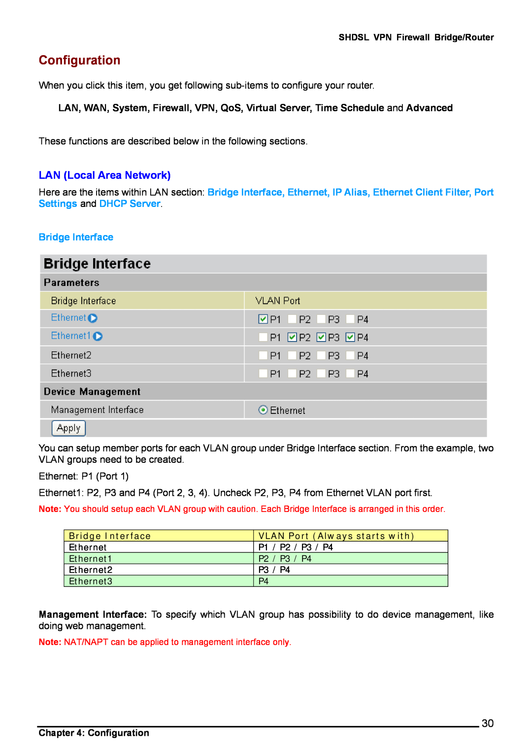
LAN Local Area Network
Configuration
Bridge Interface
Primary IP Address
Ethernet
IP Alias
Ethernet Client Filter Default setting is set to Disable
→ Active PC in LAN
Ethernet Client Filter
Active PC in LAN displays a list of individual Ethernet device’s IP Address & MAC Address which connecting to the router
Port Setting
DHCP Server
WAN - Wide Area Network
IP Assignment
RFC 1483 Routed Connections
All Ip Pppoe
RFC 1483 Bridged Connections
Connection
PPPoA Routed Connections
Advanced Options PPPoA
IPoA Routed Connections
PPPoE Connections
Advanced Options PPPoE
PPPoE with Pass-through Connections
Connection
Chapter 4 Configuration
Advanced Options PPPoE
Page
SHDSL - BiPAC
2-wired Mode
4-wired Mode
SHDSL - BiPAC
Time Zone
System
Remote Access
Firmware Upgrade
Backup / Restore
Restart Router
User Management
Firewall and Access Control
General Settings
Packet Filter
Protocol
Example Predefined Port Filters Rules
Table 1 Predefined Port Filter
Application
UDP17
Packet Filter - Add TCP/UDP Filter
Packet Filter - Add Raw IP Filter
Page
Example
Click Delete
Click Add TCP/UDP Filter
Configuring Packet Filter
5. The new port filter rule for HTTP is shown below
Block Duration
Intrusion Detection
Ascend Kill
Table 2 Hacker attack types recognized by the IDS
Intrusion Name
Detect Parameter
URL Filter
3. If the packet does not match either of the above two items, it is sent to the remote web server
Peer to Peer Blocking The default is set to Disabled
Instant Message Blocking The default is set to Disabled
IM / P2P Blocking
Log information can be seen in the Status - Event Log after enabling
Firewall Log
PPTP Point-to-Point Tunneling Protocol
VPN - Virtual Private Networks
PPTP Connection - Remote Access
Example Configuring a Remote Access PPTP VPN Dial-out Connection
Dial-out
Function
Configuring the PPTP VPN in the Office
Description
PPTP Connection - LAN to LAN
Example Configuring a PPTP LAN-to-LAN VPN Connection
Description
Function
Configuring PPTP VPN in the Head Office
Configuring PPTP VPN in the Branch Office
IPSec IP Security Protocol
IPSec VPN Connection
Select the Apply button to apply your changes
IKE Proposal
Advanced Option
Ping to the IP
Local ID
Remote ID
Ping to Keep Alive
Tunnel mode ESPMD5 with AES
Table 3 Network Configuration and Security Plan
Example Configuring a IPSec LAN-to-LAN VPN Connection
192.168.0.0/24 69.1.121.30 192.168.1.0/24 69.1.121.3 12345678
Configuring IPSec VPN in the Head Office
Configuring IPSec VPN in the Branch Office
Example Configuring a IPSec Host-to-LAN VPN Connection
Configuring IPSec VPN in the Office
L2TP Layer Two Tunneling Protocol
L2TP VPN Connection
L2TP Connection - Remote Access
L2TP over IPSec L2TP/IPSec VPN Connection
Example Configuring a L2TP VPN - Remote Access Dial-in Connection
Dial-in
Configuring L2TP VPN in the Office
Example Configuring a Remote Access L2TP VPN Dial-out Connection
Configuring the L2TP VPN in the Office
Example Configuring your Router to Dial-in to the Server
L2TP Connection - LAN to LAN
L2TP over IPSec L2TP/IPSec VPN Connection
Example Configuring L2TP LAN-to-LAN VPN Connection
Configuring L2TP VPN in the Head Office
Configuring L2TP VPN in the Branch Office
High
QoS Quality of Service
Click Clear
Prioritization
Standard DSCP
Table 4 DSCP Mapping Table
DSCP Mapping Table
SHDSL Router Device
Outbound IP Throttling LAN to WAN
Inbound IP Throttling WAN to LAN
Example QoS for your Network
VoIP Normal PCs Restricted PC
Connection Diagram
Information and Settings
Restricted Application
Advanced setting by using IP throttling
Mission-critical application
Voice application
SHDSL VPN Firewall Bridge/Router
Virtual Server “Port Forwarding”
Internal IP
Add Virtual Server
IP Address
Example
Edit DMZ Host
Global IP Address
Edit One-to-One NAT Network Address Translation
Select the Apply button to apply your changes
Protocol
Table 5 Well-known and registered Ports
Example List of some well-known and registered port numbers
Port Number
Time Schedule
Delete a Time Slot
Click Edit
Configuration of Time Schedule
Edit a Time Slot
Management, IGMP and VLAN Bridge Static Route
Advanced
Dynamic DNS
Check Email
Embedded Web Server 2 Management IP accounts
Device Management
SNMP Version SNMPv2c and SNMPv3
Universal Plug and Play UPnP
SNMP V1 and
SNMP
From RFC 1472 PPP/Security MIB
From RFC1650 EtherLike-MIB
From RFC 1493 Bridge MIB
From RFC 1471 PPP/LCP MIB
IGMP
Advanced VLAN Setup Example Triply Play
Step 1 Setup Member Ports
Go to Configuration LAN Bridge Interface
Step 2 Create WAN Interface
Go to Configuration WAN ISP
Bridge Interface
VLAN Port Always starts with
Pppoe
Go to Configuration Advanced VLAN Bridge
Step 3 Setup VLAN Service
From the example
Step 4 IGMP Snooping Enable
Save Configuration to Flash
Go Configuration Advanced IGMP
Logout
Problems with the LAN Interface
Chapter 5 Troubleshooting
Problems starting up the router
Problems with the WAN Interface
Contact Billion AUSTRALIA
APPENDIX A Product Support and Contact Information
WORLDWIDE
Top
Page
Image
Contents