Manuals
/
Bissell
/
Household Appliance
/
Water Pump
Bissell
instruction manual
V Wiring Diagram HS-20 Diffusion Pump
Models:
HS-20
1
25
43
43
Download
43 pages
32.09 Kb
22
23
24
25
26
27
28
29
Troubleshooting
Specs
Warranty
Maintenance
Sight Glass Assembly
START-UP Procedure
Cleaning a NEW Pump
Heater Replacement
Sales and Service Offices
Thermal Switches
Page 25
Image 25
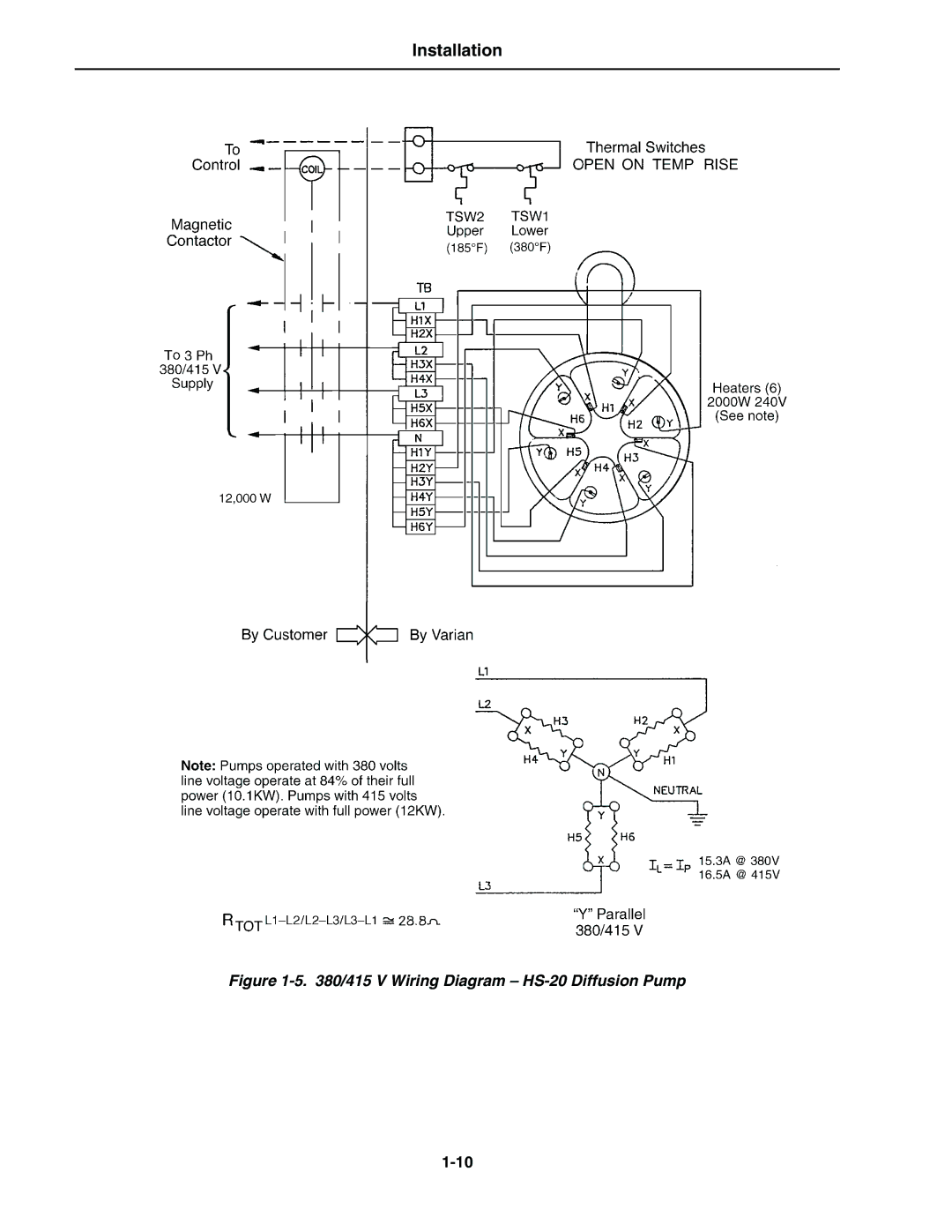
Installation
Figure
1-5.
380/415 V Wiring Diagram –
HS-20
Diffusion Pump
1-10
Page 24
Page 26
Page 25
Image 25
Page 24
Page 26
Contents
HS-20 Diffusion Pump
Sales and Service Offices
Telephone Numbers
Warranty Replacement and Adjustment
Warranty
Page
Page
Iii
Prohibited Action Explosion-Causing Condition
Prohibited Action Result
Page
Vii
Page
Page
Section Safety Considerations Section I Installation
Table of Contents
List of Tables
List of Illustrations
Operating Specifications See Figure
Installation General
Model Technical Specifications
ASA
Outline Drawing HS-20 Diffusion Pump, with ASA Flanges
Unpacking
Cleaning a NEW Pump
Installation
Utility and System Connections
Safety Considerations and Interlocks
Vacuum Connections
Cooling Water Connections See Figure
Cooling Water Connections
Initial Vacuum Test
Thermal Switches
240/400/430/440/480 V Wiring Diagram HS-20 Diffusion Pump
415 V Wiring Diagram HS-20 Diffusion Pump
Adding Pump Fluid
Sight Glass Assembly
Operation
START-UP Procedure
Operation
Shutdown Procedure
Periodic Inspection
Maintenance General
Cleaning
Maintenance
Do not overtighten the screw
Disassembling and Reassembling the Cold CAP Refer to Figure
External Fittings Cold Cap Assembly
Disassembling the Jet Assembly Refer to Figure
JET Assembly
Disassembling the Lower Jet Assembly
Inch Jet Assembly
Reassembling the Jet Assembly
Maintenance Reassembling the Lower Jet Assembly
Heater Replacement
Jet Coupling
Tighten clamping nuts to 250 in.-lbs
Maintenance
Replaceable Parts
Maintenance
Outgassing
Troubleshooting Leakage
Poor Pump or System Performance
Troubleshooting
Top
Page
Image
Contents