USEMakeOFsureEXTENSIONthe extensionCORDScord is in good condition before using. Always use the proper size extension cords with the tool – that is, proper wire size for various lengths of cord and heavy enough to carry the current the tool will draw. Use of an undersized cord will cause a drop in line voltage resulting in loss of power and overheating. For proper size cords see chart below.
120V |
| Minimum Gauge for Cord Sets | ||||
| ||||||
Volts |
|
| Total Length of Cord in Feet | |||
240V |
| |||||
| ||||||
Ampere Ra | ||||||
More |
| Not more | American Wire Gage |
| ||
Than | - | Than | 18 | 16 | 16 | 14 |
0 | 6 | |||||
6 | - | 10 | 18 | 16 | 14 | 12 |
10 | - | 12 | 16 | 16 | 14 | 12 |
12 | - | 16 | 14 | 12 | Not Recommended | |
MOTORBe sure your power supply agrees with nameplate marking. 120 Volts AC only means your tool will operate on standard 60 Hz household power. Do not operate AC tools on DC. A rating of 120 volts AC/DC means that you tool will operate on standard 60 Hz AC or DC power. This information is printed on the nameplate. Lower voltage will cause loss of power and can result in
FUNCTIONAL DESCRIPTION | A |
| 5 3 | |
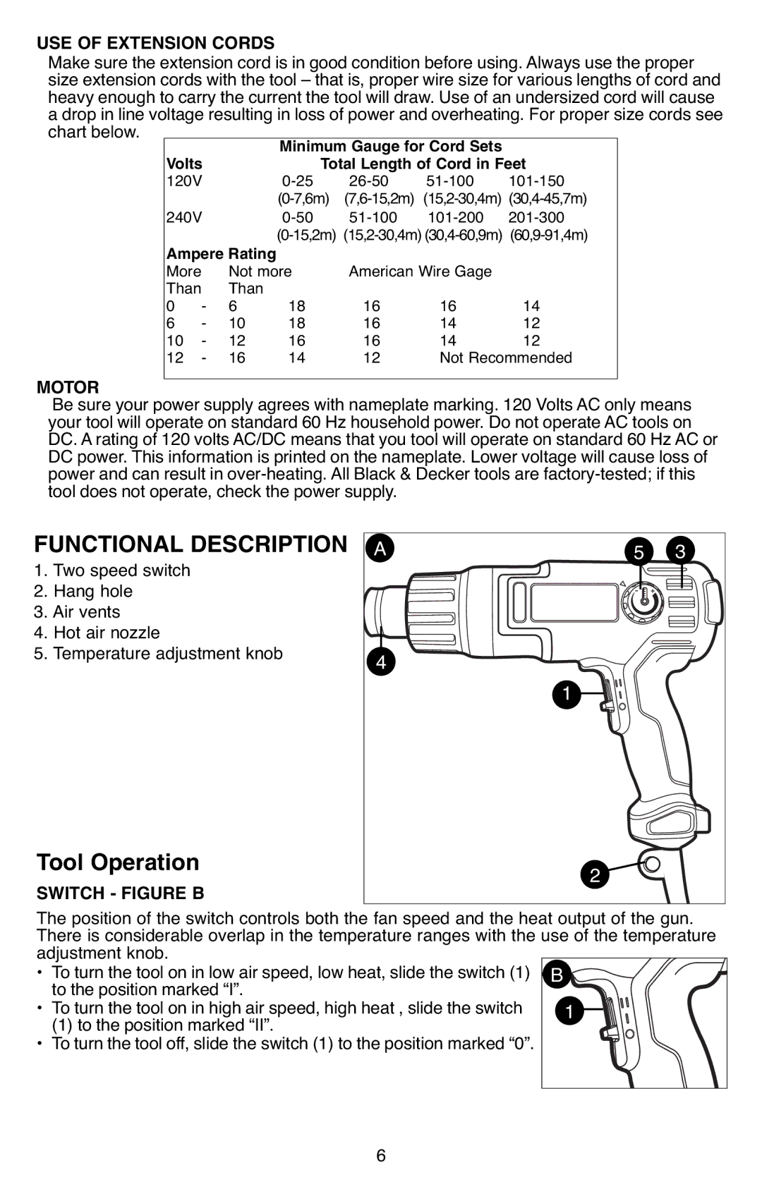
1. | Two speed switch |
| ||
2. | Hang hole |
|
|
|
3. Air vents |
|
|
| |
4. | Hot air nozzle | 4 |
|
|
5. | Temperature adjustment knob | 1 | ||
|
|
| ||
Tool Operation |
|
| 2 | |
|
|
| ||
The position of the switch controls both the fan speed and the heat output of the gun. | ||||
SWITCH - FIGURE B |
|
|
| |
There is considerable overlap in the temperature ranges with the use of the temperature | ||||
adjustment knob. |
| B |
| |
• | Toturn the tool on in low air speed, low heat, slide the switch (1) |
| ||
• | to the position marked “I”. |
|
| |
Toturn the tool on in high air speed, high heat , slide the switch |
| 1 | ||
| (1) to the position marked “II”. |
|
| |
• Toturn the tool off, slide the switch (1) to the position marked “0”. |
|
| ||
6
