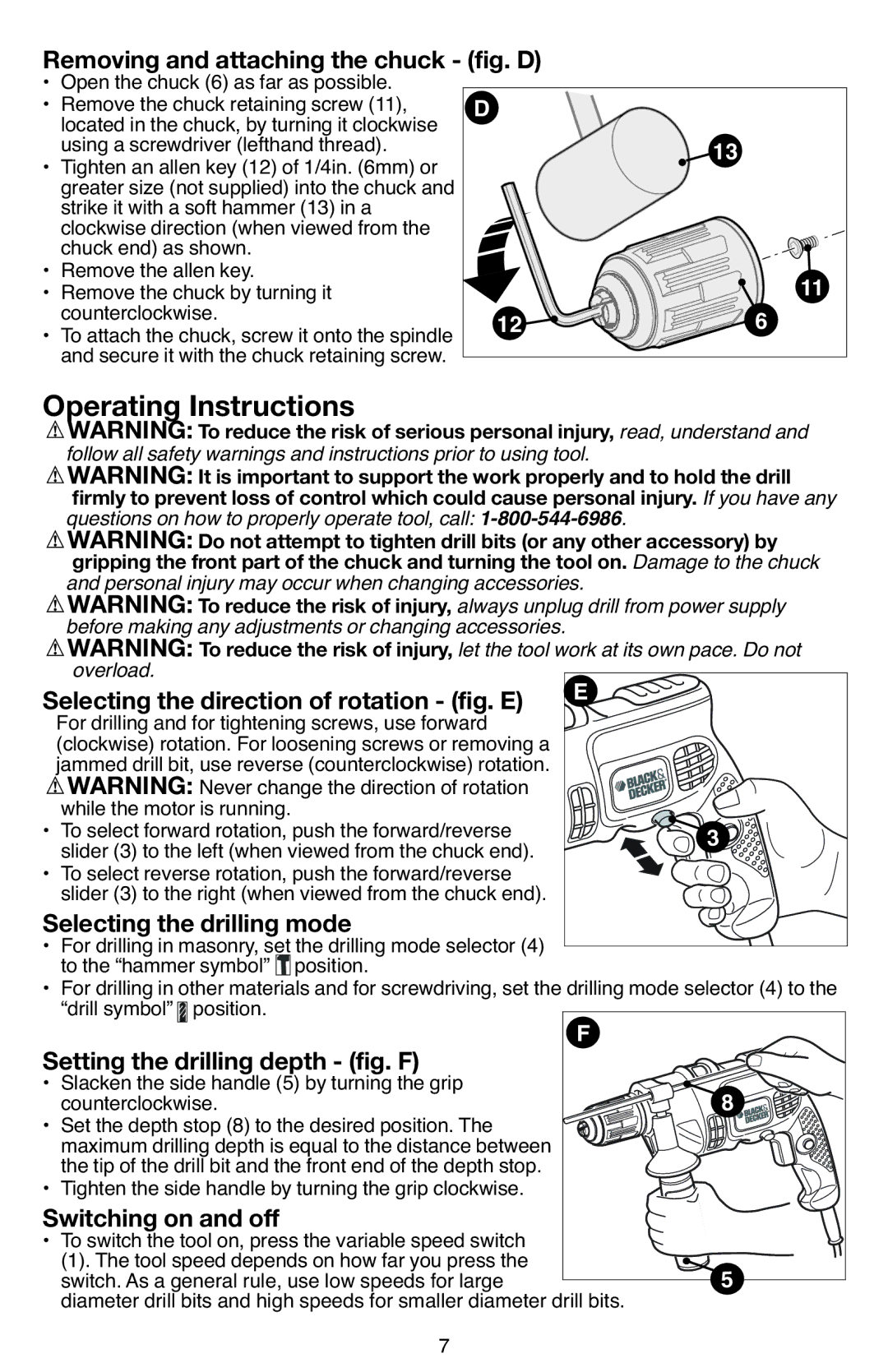
• | Open the chuck (6) as far as possible. |
|
|
|
Removing and attaching the chuck - (fig. D) |
|
| ||
• | Remove the chuck retaining screw (11), |
|
|
|
D |
|
| ||
| located in the chuck, by turning it clockwise |
|
| |
• | using a screwdriver (lefthand thread). |
| 13 |
|
Tighten an allen key (12) of 1/4in. (6mm) or |
|
| ||
| greater size (not supplied) into the chuck and |
|
|
|
| strike it with a soft hammer (13) in a |
|
|
|
| clockwise direction (when viewed from the |
|
|
|
• | chuck end) as shown. |
|
|
|
Remove the allen key. |
|
| 11 | |
• | Remove the chuck by turning it |
|
| |
• | counterclockwise. | 12 | 6 |
|
To attach the chuck, screw it onto the spindle |
| |||
| and secure it with the chuck retaining screw. |
|
|
|
|
|
|
| |
Operating Instructions |
|
| ||
| WARNING: To reduce the ri k of serious personal injury, read, understand and | |||
| follow all safety warnings and instructions prior to using tool. |
| ||
| WARNING: It is important to support the work properly and to hold the drill | |||
| questions on how to properly operate tool, |
| ||
| firmly to prevent loss of control which could cause personal injury. If you have any | |||
| gripping the front p rt of the chuck and turning the tool on. Damage to the chuck | |||
| WARNING: Do not attempt to tighten drill bits (or any other ccess ry) by | |||
| and personal injury may occur when changing accessories. |
| ||
| WARNING: To re ce the risk of i jury, always unplug drill frompower supply | |||
| before making any adjustments or changing accessories. |
|
| |
| WARNING: To reduce the risk of injury, let the tool work at itsown pace. Do not | |||
| overload. |
| E |
|
| For drilling and for tightening screws, use forward |
| ||
Selecti | the direction ofrotation - (fig. E) |
| ||
| (clockwise) rotation. For loosening screws or removing a |
|
| |
| jammed drill bit, use reverse (counterclockwise) rotation. |
|
| |
| WARNING: Never change the direction of rotation |
|
| |
• | while the motor is running. |
| 3 | |
To select forward rotation, push the forward/reverse |
| |||
| slider (3) to the left (when viewed from the chuck end). |
|
| |
• To select reverse rotation, push the forward/reverse |
|
| ||
• | slider (3) to the right (when viewed from the chuck end). |
|
| |
For drilling in masonry, set the drilling mode selector (4) |
|
| ||
Selecting the drillingmode |
|
| ||
| to the “hammer symbol” position. |
|
| |
• For drilling in other materials and forscrewdriving, set the drilling modeselector (4) to the | ||||
• | “drill symbol” position. | F |
| |
Slacken the side handle (5) by turning the grip |
| |||
Setting t | e drilling depth - (f g. F) | 8 | ||
• | counterclockwise. |
| ||
Set the depth stop (8) to the desired position. The |
|
| ||
| maximum drilling depth is equal to the distance between |
|
| |
• | the tip of the drill bit and the front end of the depth stop. |
|
| |
Tighten the side handle by turning the grip clockwise. |
|
| ||
• To switch the tool on, press the variable speed switch |
|
| ||
Switching on and off |
|
| ||
| (1). The tool speed depends on how far you press the |
| 5 | |
| switch. As a general rule, use low speeds for large |
| ||
| diameter drill bits and high speeds for smaller diameter drill bits. |
| ||
|
| 7 |
|
|