SYMBOLS |
|
|
|
|
|
|
|
|
|
|
The label on your tool may include the following symbols | amperes | |||||||||
V |
|
| volts |
|
| A | ||||
Hz |
|
| hertz |
|
| W | watts | |||
min |
|
| minutes |
| no | alternating current | ||||
...................... |
|
| direct current | no load speed | ||||||
.......................... |
|
| Class II Construction |
|
| ........................ | earthingterminal | |||
........................ |
|
| safety alert symbol | ...................../min | revolutions or | |||||
USE OF EXTENSION CORDS |
|
| reciprocations per minute | |||||||
Make sure the extension cord is in good condition before using. Always use the proper | ||||||||||
size extension cords with the tool – that is, proper wire size for various lengths of cord and | ||||||||||
heavy enough to carry the current the tool will draw. Use of an undersized cord will cause | ||||||||||
a drop in line voltage resulting in loss of power and overheating. For proper size cords see | ||||||||||
chart below. |
|
|
|
|
|
| ||||
120V |
| Minimum Gauge for Cord Sets |
| |||||||
|
|
| ||||||||
| Volts |
|
| Total Length of Cord in Feet |
| |||||
| 240V |
|
| |||||||
|
|
| ||||||||
| Ampere Ra |
| ||||||||
| More |
| Not more | American Wire Gauge |
|
| ||||
| Than | - | Than | 18 | 16 | 16 |
| 14 |
| |
| 0 | 6 |
|
| ||||||
| 6 | - | 10 | 18 | 16 | 14 |
| 12 |
| |
MOTOR | 10 | - | 12 | 16 | 16 | 14 |
| 12 |
| |
12 | - | 16 | 14 | 12 | Not Recommended |
| ||||
Be sure your power supply agrees with nameplate marking. 120 Volts AC only means your | ||||||||||
tool will operate on standard 60 Hz household power. Do not operate AC tools on DC. A | ||||||||||
rating of 120 volts AC/DC means thatyou tool will operate on standard 60 Hz AC orDC | ||||||||||
power. This information is printed on the nameplate. Lower voltage will causeloss of | ||||||||||
power and can result in | ||||||||||
tool does not operate, check the powersupply. |
|
|
|
|
| |||||
| SAVE THESE INSTRUCTIONS | |||||||||
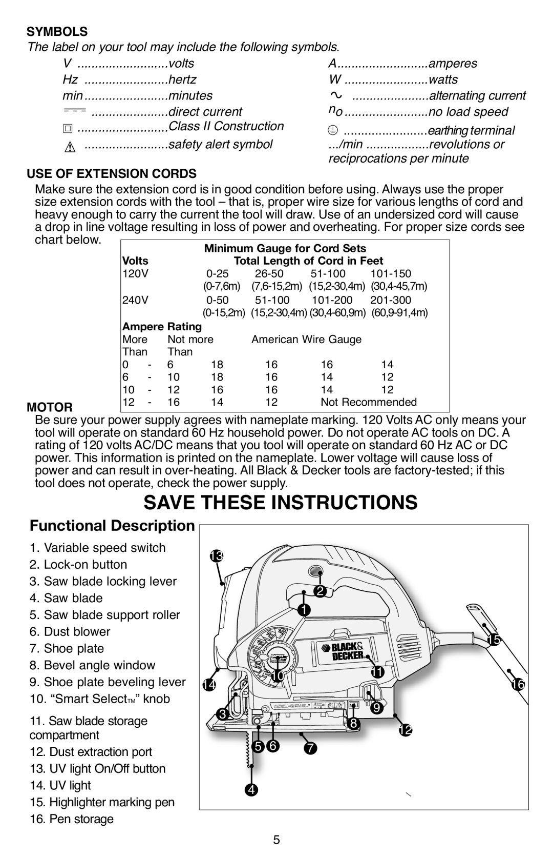
Functional Description 1. Variable speed switch
2.
3. Saw blade locking lever
4. Saw blade
5. Saw blade support roller
6. Dust blower
7. Shoe plate
8. Bevel angle window
9. Shoe plate beveling lever
10. “Smart SelectTM” knob
11. Saw blade storage compartment
12. Dust extraction port
13. UV light On/Off button
14. UV light
15. Highlighter marking pen
16. Pen storage
13 |
|
| 2 |
|
|
|
| 1 |
| 15 | |
| 10 |
|
| 11 | |
14 |
|
| 16 | ||
3 | 6 | 7 | 8 | 9 | 12 |
5 |
|
|
| ||
4 |
|
|
|
|
|
| 5 |
|
|
|
|
