PSL12 specifications
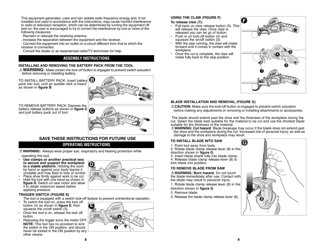
The Black & Decker PSL12 is a powerful and versatile 12-volt cordless screwdriver designed to make various DIY projects and tasks easier and more efficient. It is ideal for both home improvement enthusiasts and professionals alike, providing a convenient solution for fastening screws and assembling furniture.One of the standout features of the PSL12 is its compact and lightweight design. Weighing in at just over 1 pound, this tool is easy to maneuver and can be operated with one hand, making it perfect for tasks that require precision and control in tight spaces. The ergonomic handle ensures a comfortable grip, reducing fatigue during extended use.
The PSL12 operates on a 12-volt lithium-ion battery, which offers sufficient power to tackle a wide range of applications. Lithium-ion technology provides a consistent level of performance and does not suffer from memory effect, allowing users to recharge the battery at any time without worrying about reducing its lifespan. The battery typically delivers a longer runtime compared to standard nickel-cadmium batteries, enabling users to complete their projects without frequent interruptions.
Another notable feature is its variable speed control, which allows users to adjust the speed setting to suit different materials and tasks. This flexibility is essential for achieving the desired torque when driving screws into various substrates, including wood, metal, and plastic. The built-in LED work light illuminates dark or confined spaces, ensuring visibility during tasks, even in dimly lit areas.
The PSL12 is equipped with a magnetic bit holder, which facilitates quick and effortless bit changes. This feature is particularly useful when transitioning between different jobs or projects, saving time and effort. The tool also includes a reverse switch, allowing for easy removal of screws and providing greater control during operation.
Moreover, the Black & Decker PSL12 boasts a durable construction designed to withstand the rigors of everyday use. This reliability, combined with its excellent performance and user-friendly features, makes it a popular choice among DIY enthusiasts and professionals seeking a dependable cordless screwdriver.
Overall, the Black & Decker PSL12 combines power, portability, and convenience, making it an essential tool for a variety of projects. Whether assembling furniture, installing fixtures, or performing general repair tasks, the PSL12 delivers the performance and reliability users need to get the job done efficiently.

