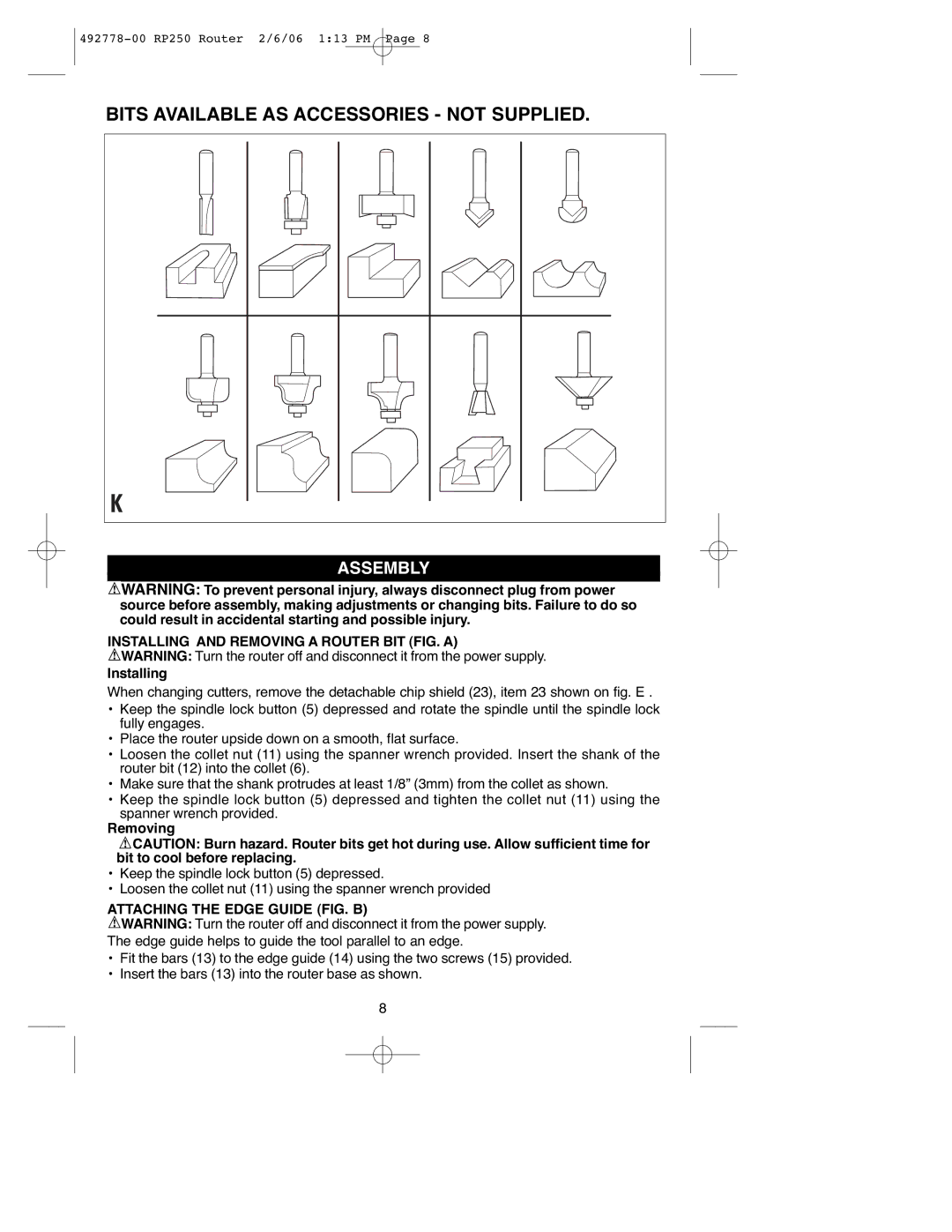
BITS AVAILABLE AS ACCESSORIES - NOT SUPPLIED.
ASSEMBLY |
![]() WARNING: To prevent personal injury, always disconnect plug from power source before assembly, making adjustments or changing bits. Failure to do so could result in accidental starting and possible injury.
WARNING: To prevent personal injury, always disconnect plug from power source before assembly, making adjustments or changing bits. Failure to do so could result in accidental starting and possible injury.
INSTALLING AND REMOVING A ROUTER BIT (FIG. A)
![]() WARNING: Turn the router off and disconnect it from the power supply.
WARNING: Turn the router off and disconnect it from the power supply.
Installing
When changing cutters, remove the detachable chip shield (23), item 23 shown on fig. E .
•Keep the spindle lock button (5) depressed and rotate the spindle until the spindle lock fully engages.
•Place the router upside down on a smooth, flat surface.
•Loosen the collet nut (11) using the spanner wrench provided. Insert the shank of the router bit (12) into the collet (6).
•Make sure that the shank protrudes at least 1/8” (3mm) from the collet as shown.
•Keep the spindle lock button (5) depressed and tighten the collet nut (11) using the spanner wrench provided.
Removing
![]() CAUTION: Burn hazard. Router bits get hot during use. Allow sufficient time for bit to cool before replacing.
CAUTION: Burn hazard. Router bits get hot during use. Allow sufficient time for bit to cool before replacing.
•Keep the spindle lock button (5) depressed.
•Loosen the collet nut (11) using the spanner wrench provided
ATTACHING THE EDGE GUIDE (FIG. B)
![]() WARNING: Turn the router off and disconnect it from the power supply. The edge guide helps to guide the tool parallel to an edge.
WARNING: Turn the router off and disconnect it from the power supply. The edge guide helps to guide the tool parallel to an edge.
•Fit the bars (13) to the edge guide (14) using the two screws (15) provided.
•Insert the bars (13) into the router base as shown.
8
