PSD-4 AND PSD-8
3. Installation
3.1 Choosing a Site
•The PSD must be installed within five feet (1.5 m) of a grounded AC outlet.
•The PSD must be within 50 feet (15 m) of the equipment that will be attached to the main channel and each
•Allow 36 inches (91 cm) frontal clearance for operating and maintenance accessibility.
•Allow four inches (10 cm)
•
3.2 Configuring the PSD Printed Circuit Board
Table 1 on the following page explains each of the configurable jumpers or switches on the PSD printed circuit board. Figures 3 and 4 show the locations of each of the jumpers and switches for the
There are two EXT. BUFFER switches on the
Switch S1 controls the buffer for
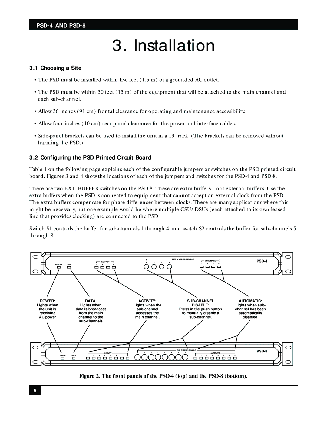
POWER: | DATA: | ACTIVITY: | AUTOMATIC: | |
Lights when | Lights when | Lights when the | DISABLE: | Lights when sub- |
the unit is | data is broadcast | Press in the push button | channel has been | |
receiving | from the main | accesses the | to manually disable a | automatically |
AC power | channel to the | main channel. | disabled. | |
|
|
|
|
Figure 2. The front panels of the PSD-4 (top) and the PSD-8 (bottom).
6