MED100A-0908-3/5

p/n 6132r3

RS-422/RS-485 Mode

Selection

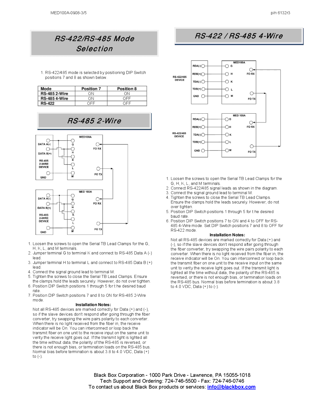
1.RS-422/485 mode is selected by positioning DIP Switch positions 7 and 8 as shown below.


Mode

Position 7

Position 8


RS-485 2-Wire

ON

ON


RS-485 4-Wire

ON

OFF


RS-422

OFF

OFF


RS-485 2-Wire

1.Loosen the screws to open the Serial TB Lead Clamps for the G, H, K, L, and M terminals.

2.Jumper terminal G to terminal K and connect to RS-485 Data A (-) lead.

3.Jumper terminal H to terminal L and connect to RS-485 Data B (+) lead.

4.Connect the signal ground lead to terminal M.

5.Tighten the screws to close the Serial TB Lead Clamps. Ensure the clamps hold the leads securely. However, do not over tighten.

6.Position DIP Switch positions 1 through 5 for t he desired baud rate.

7.Position DIP Switch positions 7 and 8 to ON for RS-485 2-Wire mode.

Installation Notes:

Not all RS-485 devices are marked correctly for Data (+) and (-), so if the slave devices don’t respond after going through the fiber converter, try swapping the wire pairs polarity to each converter. When there is no light received from the fiber in, the receive indicator will be On. You can interconnect or loop back the transmit fiber on one unit to the receive input on the same unit to verity the receive light goes out. If the transmit light is lighted all the time without data, the polarity of the RS-485 is reversed, or there is not enough bias, or termination loads on the RS-485 bus. Normal bias before termination is about 3.8 to 4.0 VDC, Data (+) to (-).

RS-422 / RS-485 4-Wire

1.Loosen the screws to open the Serial TB Lead Clamps for the G, H, K, L, and M terminals.

2.Connect RS-422/485 signal leads as shown in the diagram.

3.Connect the signal ground lead to terminal M.

4.Tighten the screws to close the Serial TB Lead Clamps. Ensure the clamps hold the leads securely. However, do not over tighten.

5.Position DIP Switch positions 1 through 5 for t he desired baud rate.

6.Position DIP Switch positions 7 to ON and 4 to OFF for RS- 485 4-Wire mode. Set DIP Switch positions 7 and 8 to OFF for

RS-422 mode.

Installation Notes:

Not all RS-485 devices are marked correctly for Data (+) and (-), so if the slave devices don’t respond after going through the fiber converter, try swapping the wire pairs polarity to each converter. When there is no light received from the fiber in, the receive indicator will be On. You can interconnect or loop back the transmit fiber on one unit to the receive input on the same unit to verity the receive light goes out. If the transmit light is lighted all the time without data, the polarity of the RS-485 is reversed, or there is not enough bias, or termination loads on the RS-485 bus. Normal bias before termination is about 3.8 to 4.0 VDC, Data (+) to (-).

Black Box Corporation - 1000 Park Drive - Lawrence, PA 15055-1018

Tech Support and Ordering: 724-746-5500 - Fax: 724-746-0746

To contact us about Black Box products or services: info@blackbox.com

Page 3
Image 3
Black Box Industrial Serial to Multi-mode Fiber Optic Converter, MED100A RS-422/RS-485 Mode Selection, RS-485 2-Wire

MED100A, Industrial Serial to Multi-mode Fiber Optic Converter specifications

The Black Box Industrial Serial to Multi-mode Fiber Optic Converter, MED100A, is an essential device designed to bridge the gap between Serial RS-232 or RS-422/485 interfaces and multi-mode fiber optic cabling. As industries evolve, the necessity for reliable and high-performance data transmission over longer distances becomes increasingly critical. The MED100A addresses this need by providing a seamless method for converting electrical signals to optical signals, enabling robust communication across extensive networks.

One of the key features of the MED100A is its ability to extend communication distances significantly beyond the limitations of standard copper connections. While traditional copper cabling can handle distances of up to 1,200 meters, the MED100A can transmit data over multi-mode fiber optic cables for distances up to 2 kilometers. This capability makes it ideal for industrial environments, where equipment may be scattered over vast areas.

The MED100A supports multiple serial standards including RS-232, RS-422, and RS-485, making it versatile for various applications. Its auto-transceiver feature allows automatic configuration for half or full-duplex transmission, reducing the need for manual adjustments and facilitating ease of use. The device also includes baud rate settings ranging from 300 bps to 115.2 kbps, accommodating a wide variety of devices and ensuring compatibility across different systems.

In terms of durability, the MED100A is built for industrial environments. It boasts an IP30-rated metal housing, which protects it from dust and physical damage. The device operates efficiently in a temperature range of -40 to 85 degrees Celsius, making it suitable for challenging applications such as factory automation, process control, and utility monitoring.

Powering the MED100A is straightforward, as it can be powered either by an external power supply or through Power over Ethernet (PoE), providing flexibility in installation. Additionally, LED indicators for power, data transmission, and signal integrity allow for easy monitoring and troubleshooting.

In conclusion, the Black Box Industrial Serial to Multi-mode Fiber Optic Converter, MED100A, stands out for its robust performance, extensive distance capabilities, and adaptability to various serial protocols. Its rugged design and installation flexibility confirm its position as a reliable tool for modern industrial communication requirements.