
MPSH8-S20-120V, MPSH8-D20-120V, Outlet Managed PDU, MPSH8-D20-208+V, MPSH16-D20-120V specifications
The Black Box MPSH Series, specifically the MPSH16-D20-208+V, MPSH8-S20-208+V, MPSH16-D20-120V, and MPSH8-D20-208+V, represents a state-of-the-art solution in the realm of Outlet Managed Power Distribution Units (PDUs). Designed for seamless integration within data centers and server rooms, these PDUs are engineered to support the ever-evolving demands of modern IT infrastructures while ensuring energy efficiency and optimal performance.One of the hallmark features of the MPSH series is its robust management capabilities. These PDUs allow for individual outlet monitoring and control, enabling IT managers to efficiently manage power consumption across various devices. This granular control helps in identifying underutilized equipment, managing power distribution more effectively, and ultimately lowering operational costs.
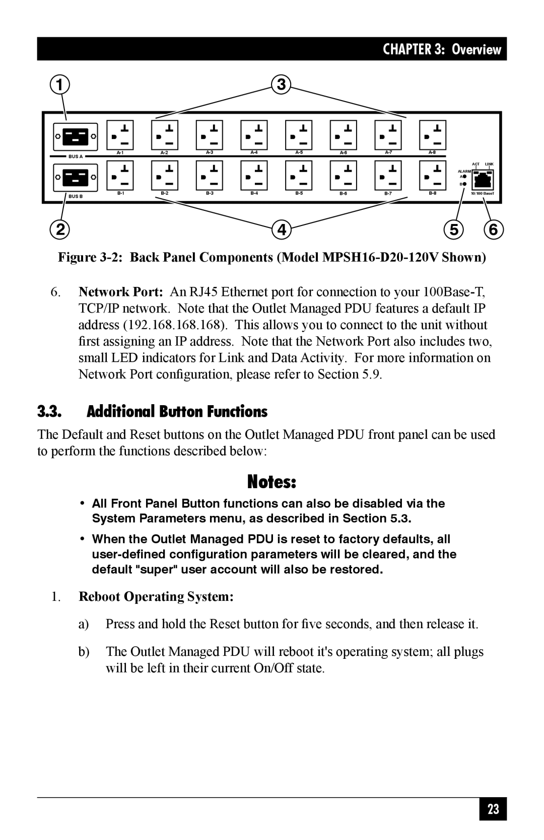
In terms of connectivity, the MPSH units are equipped with multiple outlets—providing flexibility to connect numerous devices. The MPSH16-D20-208+V, for instance, features sixteen outlets, while the MPSH8 series boasts eight. This variety allows for customization based on specific needs in different settings, whether it is a small server room or a large data center.
The MPSH PDUs also incorporate advanced technologies to enhance power efficiency and reliability. They are equipped with features such as surge protection, which shields sensitive equipment from voltage spikes, and power factor correction, which optimizes energy usage for improved efficiency. Additionally, remote management capabilities enable IT personnel to access power metrics and control outlet status from any location via a secure web interface, providing enhanced visibility and proactive management of power flows.
Safety and compliance are paramount in the design of the MPSH series. These PDUs adhere to industry standards, ensuring that they meet the necessary regulations for quality and safety, which is critical in preventing downtime and electrical hazards.
Moreover, the installation process for MPSH PDUs is straightforward, facilitating quick deployment within existing infrastructures. Their compact design allows for mounting in various configurations, maximizing space efficiency in crowded server racks.
Overall, the Black Box MPSH16-D20-208+V, MPSH8-S20-208+V, MPSH16-D20-120V, and MPSH8-D20-208+V Outlet Managed PDUs deliver a blend of functionality, efficiency, and safety, making them an indispensable asset for organizations looking to optimize their power management strategies in today’s data-driven environment.