CONNECTIONS & CONTROLS
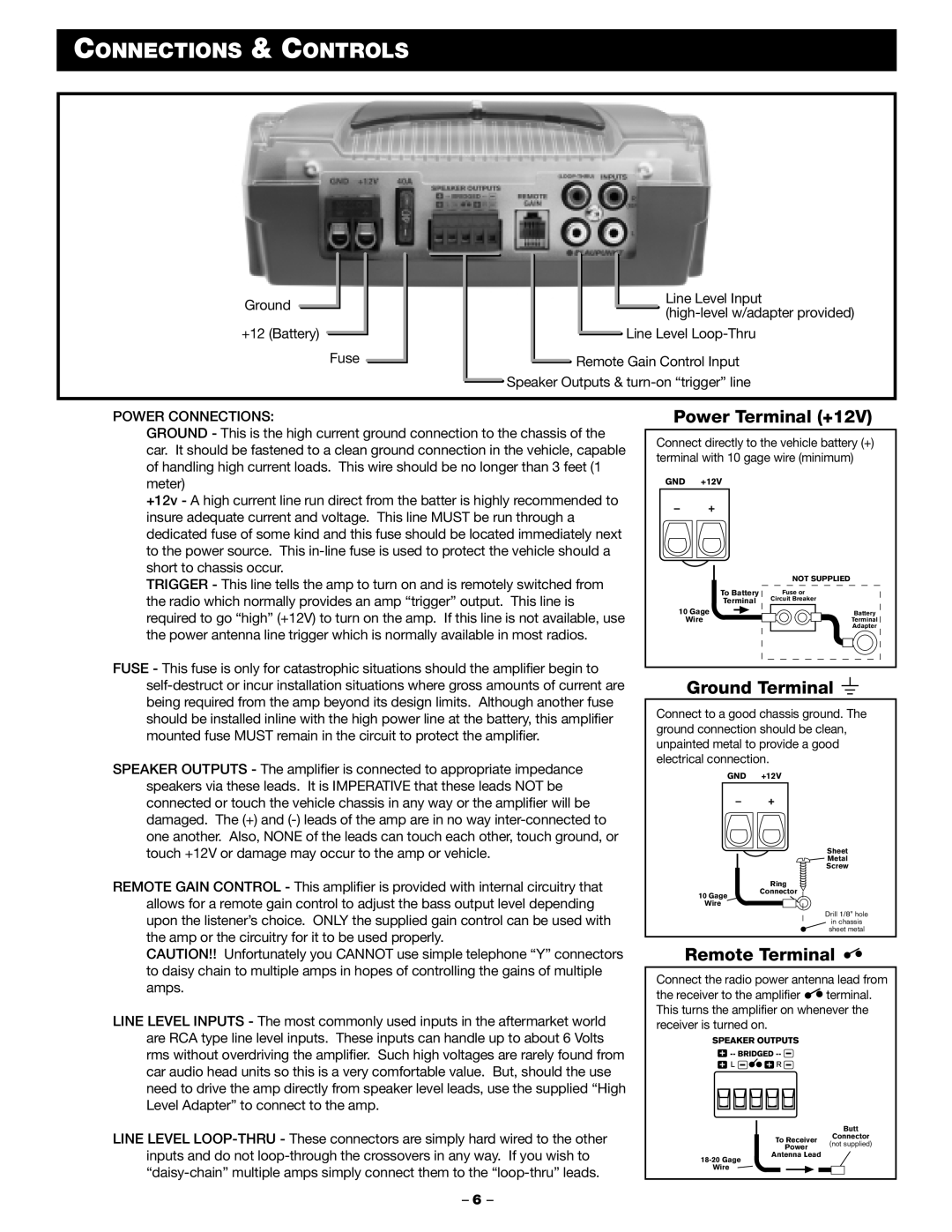
Ground
+12 (Battery)
Fuse
Line Level Input
![]() Line Level
Line Level
![]() Remote Gain Control Input
Remote Gain Control Input
![]() Speaker Outputs &
Speaker Outputs &
POWER CONNECTIONS:
GROUND - This is the high current ground connection to the chassis of the car. It should be fastened to a clean ground connection in the vehicle, capable of handling high current loads. This wire should be no longer than 3 feet (1 meter)
+12v - A high current line run direct from the batter is highly recommended to insure adequate current and voltage. This line MUST be run through a dedicated fuse of some kind and this fuse should be located immediately next to the power source. This
TRIGGER - This line tells the amp to turn on and is remotely switched from the radio which normally provides an amp “trigger” output. This line is required to go “high” (+12V) to turn on the amp. If this line is not available, use the power antenna line trigger which is normally available in most radios.
FUSE - This fuse is only for catastrophic situations should the amplifier begin to
SPEAKER OUTPUTS - The amplifier is connected to appropriate impedance speakers via these leads. It is IMPERATIVE that these leads NOT be connected or touch the vehicle chassis in any way or the amplifier will be damaged. The (+) and
Power Terminal (+12V)
Connect directly to the vehicle battery (+) terminal with 10 gage wire (minimum)
GND +12V
| NOT SUPPLIED |
To Battery | Fuse or |
Terminal | Circuit Breaker |
10 Gage | Battery |
Wire | Terminal |
| Adapter |
Ground Terminal 
Connect to a good chassis ground. The ground connection should be clean, unpainted metal to provide a good electrical connection.
GND +12V
touch +12V or damage may occur to the amp or vehicle.
REMOTE GAIN CONTROL - This amplifier is provided with internal circuitry that allows for a remote gain control to adjust the bass output level depending upon the listener’s choice. ONLY the supplied gain control can be used with the amp or the circuitry for it to be used properly.
10 Gage
Wire
Sheet
Metal
Screw
Ring
Connector
Drill 1/8” hole
in chassis
sheet metal
CAUTION!! Unfortunately you CANNOT use simple telephone “Y” connectors to daisy chain to multiple amps in hopes of controlling the gains of multiple amps.
LINE LEVEL INPUTS - The most commonly used inputs in the aftermarket world are RCA type line level inputs. These inputs can handle up to about 6 Volts rms without overdriving the amplifier. Such high voltages are rarely found from car audio head units so this is a very comfortable value. But, should the use need to drive the amp directly from speaker level leads, use the supplied “High Level Adapter” to connect to the amp.
LINE LEVEL
– 6 –
Remote Terminal 

Connect the radio power antenna lead from
the receiver to the amplifier ![]()
![]() terminal. This turns the amplifier on whenever the receiver is turned on.
terminal. This turns the amplifier on whenever the receiver is turned on.
|
|
|
|
|
|
| Butt | ||
| To Receiver |
|
| Connector | |||||
| (not supplied) | ||||||||
| Power | ||||||||
|
|
|
|
|
| ||||
| Antenna Lead |
|
|
|
|
| |||
|
|
|
|
| |||||
Wire |
|
|
|
|
|
|
|
| |