ENGLISH
D.Conveyor Installation
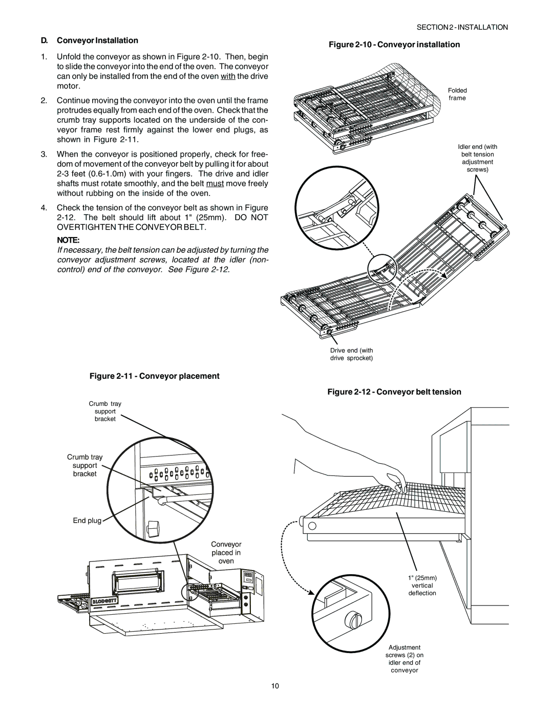
1.Unfold the conveyor as shown in Figure
2.Continue moving the conveyor into the oven until the frame protrudes equally from each end of the oven. Check that the crumb tray supports located on the underside of the con- veyor frame rest firmly against the lower end plugs, as shown in Figure
3.When the conveyor is positioned properly, check for free- dom of movement of the conveyor belt by pulling it for about
4.Check the tension of the conveyor belt as shown in Figure
NOTE:
If necessary, the belt tension can be adjusted by turning the conveyor adjustment screws, located at the idler (non- control) end of the conveyor. See Figure
Figure 2-11 - Conveyor placement
Crumb tray
support bracket
SECTION 2 - INSTALLATION
Figure 2-10 - Conveyor installation
Folded
frame
Idler end (with
belt tension adjustment screws)
Drive end (with drive sprocket)
Figure 2-12 - Conveyor belt tension
1" (25mm)
vertical
deflection
Adjustment
screws (2) on
idler end of
conveyor
10