
m-ACR 7601 specifications
Blue Sea Systems m-ACR 7601 is a sophisticated automatic charging relay designed to ensure a reliable and efficient distribution of power in marine and recreational vehicle applications. This innovative device plays a vital role in optimizing battery management systems, offering users increased functionality and safety.One of the standout features of the m-ACR 7601 is its ability to automatically combine and isolate battery banks based on charging needs. This allows for simultaneous charging of two battery banks while preventing depletion of the starting battery. The smart design ensures that the engine-starting battery remains fully charged, enhancing overall system reliability.
Another key characteristic is its use of advanced electronic circuitry, which enables seamless operation without the need for manual intervention. The m-ACR 7601 is equipped with a microprocessor-controlled system that monitors battery voltage and intelligently connects or disconnects the battery banks as required. This technology reduces the risk of overcharging and extends the lifespan of the batteries, making it a cost-effective solution for boat owners and RV enthusiasts alike.
The m-ACR 7601 features a compact design, making it suitable for a variety of installations, even in tight spaces. Its sturdy construction is marine-rated, ensuring durability in harsh marine environments. The relay is designed to withstand high humidity, saltwater exposure, and temperature fluctuations, ensuring consistent performance and reliability.
Safety is further enhanced with built-in protective features such as reverse polarity protection and an internal fuse. This helps prevent damage to the device and the batteries themselves, providing peace of mind for users.
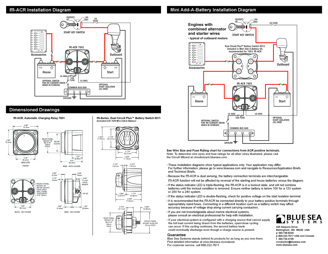
The installation of the m-ACR 7601 is straightforward, with clear wiring diagrams and mounting options for easy integration into existing systems. It is also compatible with various battery types, allowing for flexibility in battery choice according to user needs.
In summary, the Blue Sea Systems m-ACR 7601 is an advanced automatic charging relay tailored for demanding marine and recreational applications. Its intelligent battery management capabilities, robust construction, and user-friendly design make it an essential component for anyone looking to enhance their power management system onboard. With features focused on safety, efficiency, and reliability, the m-ACR 7601 stands out as a top choice for those seeking to maximize their battery performance while enjoying their time on the water or the road.