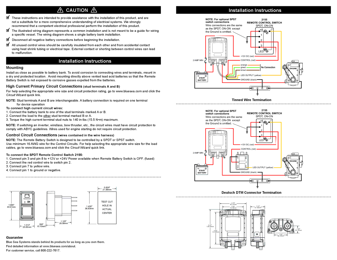
PN 7712, PN 7712100B PN 7714, PN 7712B, PN 7714B, PN 7714100B specifications
Blue Sea Systems is renowned for producing high-quality marine electrical products, and their range of circuit breakers, specifically models PN 7712B, PN 7712, PN 7714100B, PN 7712100B, PN 7714, and PN 7714B, exemplifies their commitment to safety and reliability in marine environments. Each model serves crucial functions in boat electrical systems, helping to protect against overcurrent situations that can lead to fire hazards and equipment damage.The PN 7712 and PN 7712B models are designed for higher amperage applications and feature push-to-reset technology. They are equipped with a standard actuation mechanism that allows for quick and easy resetting after a trip, ensuring minimal downtime for boat operations. These models are compact, designed to fit into standard panel cutouts, making installation straightforward while providing a clean and organized appearance.
Moving on to the PN 7714100B and PN 7712100B models, these circuit breakers come with an integrated locking mechanism, providing an additional layer of safety by preventing accidental interruptions. They are also characterized by a weather-resistant design, making them suitable for both fresh and saltwater environments. This crucial feature extends the lifespan of the circuit breakers, ensuring reliable operation despite harsh conditions.
The PN 7714 and PN 7714B models offer dual functionality – both as a circuit breaker and as a battery switch. This versatility makes them ideal for various applications on board, including powering up multiple devices without the need for additional hardware. The circuit breakers are designed with an ergonomic handle for easy operation, while visual indicators help users quickly assess the operational status of the system.
All these models are constructed from high-quality materials, ensuring robust performance and durability. They are compliant with industry standards, providing boaters with the assurance that they are investing in reliable and safe electrical solutions for their marine vessels.
In summary, Blue Sea Systems' circuit breakers PN 7712B, PN 7712, PN 7714100B, PN 7712100B, PN 7714, and PN 7714B bring together innovative design, advanced technology, and high reliability. These features not only contribute to optimal performance but also enhance safety on water, supporting boaters in their adventures with peace of mind.

