OPERATION
KNOW YOUR EQUIPMENT
READ THIS OWNER’S MANUAL AND ALL SAFETY RULES BEFORE OPERATING YOUR EQUIPMENT. Know the location and function of all features and controls on the equipment. Save this manual for future reference.
WARNING
Contact with rotating tines or other moving parts will cause serious personal injury!
Before inspecting or servicing any part of the machine, shut off engine, let all moving parts come to a complete stop, dis- connect the spark plug wire and move the wire away from the spark plug.
Engine
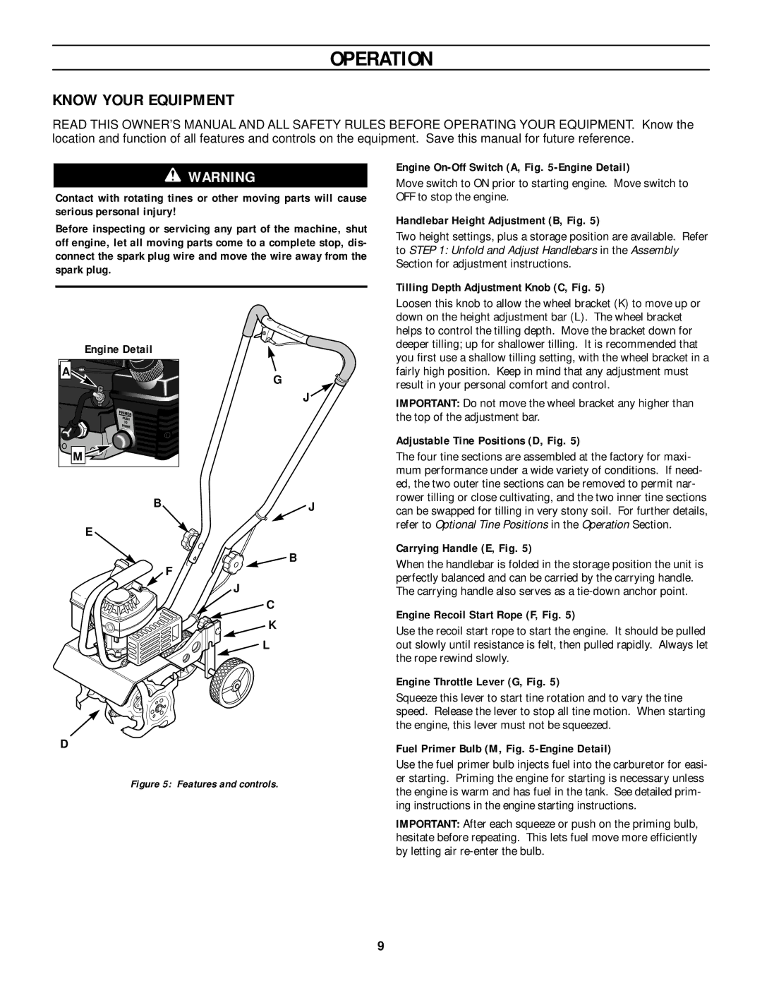
Move switch to ON prior to starting engine. Move switch to OFF to stop the engine.
Handlebar Height Adjustment (B, Fig. 5)
Two height settings, plus a storage position are available. Refer to STEP 1: Unfold and Adjust Handlebars in the Assembly Section for adjustment instructions.
Tilling Depth Adjustment Knob (C, Fig. 5)
Engine Detail
A |
M |
B
E
F
G
J ![]()
![]() J
J
![]() B
B
J
C
K
L
Loosen this knob to allow the wheel bracket (K) to move up or down on the height adjustment bar (L). The wheel bracket helps to control the tilling depth. Move the bracket down for deeper tilling; up for shallower tilling. It is recommended that you first use a shallow tilling setting, with the wheel bracket in a fairly high position. Keep in mind that any adjustment must result in your personal comfort and control.
IMPORTANT: Do not move the wheel bracket any higher than the top of the adjustment bar.
Adjustable Tine Positions (D, Fig. 5)
The four tine sections are assembled at the factory for maxi- mum performance under a wide variety of conditions. If need- ed, the two outer tine sections can be removed to permit nar- rower tilling or close cultivating, and the two inner tine sections can be swapped for tilling in very stony soil. For further details, refer to Optional Tine Positions in the Operation Section.
Carrying Handle (E, Fig. 5)
When the handlebar is folded in the storage position the unit is perfectly balanced and can be carried by the carrying handle. The carrying handle also serves as a
Engine Recoil Start Rope (F, Fig. 5)
Use the recoil start rope to start the engine. It should be pulled out slowly until resistance is felt, then pulled rapidly. Always let the rope rewind slowly.
Engine Throttle Lever (G, Fig. 5)
Squeeze this lever to start tine rotation and to vary the tine speed. Release the lever to stop all tine motion. When starting the engine, this lever must not be squeezed.
D
Figure 5: Features and controls.
Fuel Primer Bulb (M, Fig. 5-Engine Detail)
Use the fuel primer bulb injects fuel into the carburetor for easi- er starting. Priming the engine for starting is necessary unless the engine is warm and has fuel in the tank. See detailed prim- ing instructions in the engine starting instructions.
IMPORTANT: After each squeeze or push on the priming bulb, hesitate before repeating. This lets fuel move more efficiently by letting air
9