ASSEMBLY
FUEL MIXTURE CHART
(Mixture Ratio is 24 parts gasoline to 1 part
U.S. Measure | Metric Measure | ||
Gas | Oil | Petrol | Oil |
|
|
|
|
1 Gal. | 5 oz. | 4 liters | 167 ml |
2 Gal. | 11 oz. | 8 liters | 333 ml |
|
|
|
|
Fill Fuel Tank:
•Engine must be cool. Clean area around fuel tank cap and remove cap. Insert a clean funnel into the fuel tank.
•Slowly pour gasoline/oil mixture into fuel tank. Fill tank no higher than 1/2" from top of tank to allow for gasoline expan- sion. Install fuel cap and clean up any fuel spills.
STEP 4: To Make Borders and Edges,
Install the Edger Attachment
To create borders or edges near walks, driveways, flower beds, etc., you must remove the four tine sections and install the Edger Attachment (this attachment was supplied with the unit – see Page 6).
To Install the Edger Attachment:
WARNING
Contact with rotating tines or other moving parts can cause serious personal injury.
Before installing or removing attachments, or adjusting or servicing the machine, stop the engine, let all moving parts come to a complete stop, disconnect the spark plug wire and move the wire away from the spark plug.
•Collect the following parts (see Figure 4): (A) Border/Edger Tine; (B) Long Bushing; (C) Border/Edger Wheel; and (D) Short Bushing.
•Prop the machine carefully on the front of the tubular carrying handle. The work surface should be firm and flat. NOTE: Usually the Border/Edger Tine is mounted on the
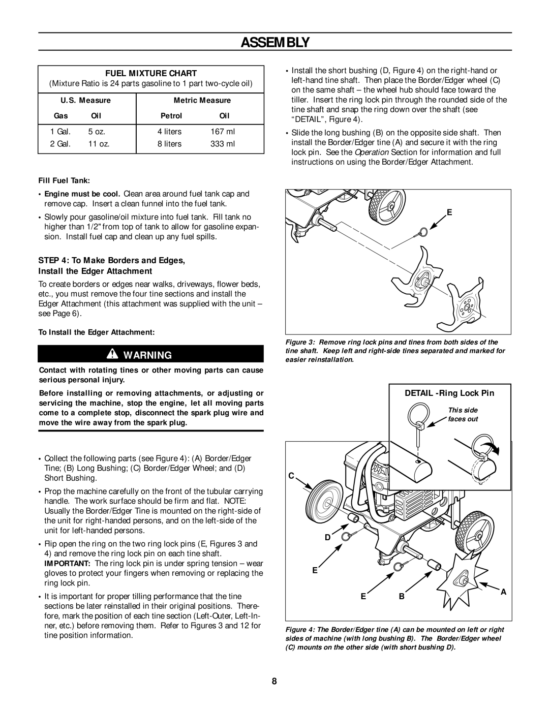
•Flip open the ring on the two ring lock pins (E, Figures 3 and 4) and remove the ring lock pin on each tine shaft. IMPORTANT: The ring lock pin is under spring tension – wear gloves to protect your fingers when removing or replacing the ring lock pin.
•It is important for proper tilling performance that the tine sections be later reinstalled in their original positions. There- fore, mark the position of each tine section
•Install the short bushing (D, Figure 4) on the
•Slide the long bushing (B) on the opposite side shaft. Then install the Border/Edger tine (A) and secure it with the ring lock pin. See the Operation Section for information and full instructions on using the Border/Edger Attachment.
E |
Figure 3: Remove ring lock pins and tines from both sides of the tine shaft. Keep left and right-side tines separated and marked for easier reinstallation.
|
| DETAIL |
|
| This side |
|
| faces out |
C |
|
|
D |
|
|
E |
|
|
E | B | A |
|
Figure 4: The Border/Edger tine (A) can be mounted on left or right sides of machine (with long bushing B). The Border/Edger wheel
(C) mounts on the other side (with short bushing D).
8