5.Each time you use the rider be sure you check the condition of the nuts, bolts, cotter pins, etc. to be sure all are tight and secure properly.
6.The transaxle transmission is
Transmission oil should be changed every 50 hours of operation or once each season.
7.The disc brake pads wear and may require
replaci ng occasionally. Th is replacement is best done by a qualified service dealer.
& CAUTION
Brakes should be kept in good oper- ating condition to avoid possible in- jury or damage to the operator or tractor.
8.Should excessive vibration develop, check for the cause immediately. Check for a damaged
blade, damaged bearing shaft, frayed belt, an obstruction, etc. DO NOT operate the rider again until the cause is found and corrected.
SPARK PLUG
The spark plug gap should be cleaned and reset to
a
the start of each mowing season.
~NOTE
Whenever the spark plug is removed for cleaning, it is advisable to re- place the spark plug gasket with a new gasket.
FIGURE 19. SPARK PLUG CLEARANCE
REPLACING BLADE
 )
) (:~~~~~~j
Before beginning work on the cutterblade, remove the spark plug fromthe
cylinder.
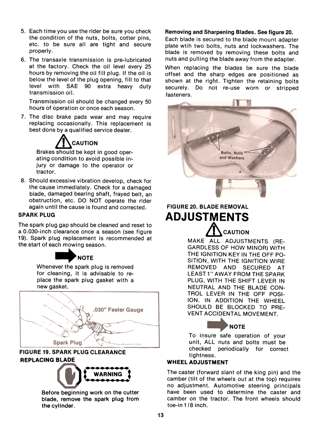
Removing and Sharpening Blades. See figure 20.
Each blade is secured to the blade mount adapter
plate wtih two bolts, nuts and lockwashers. The blade is removed by removing these bolts and nuts and pulling the blade away from the adapter.
When replacing the blades be sure the blade
offset and the sharp edges are positioned as
shown at the right. Tighten the retaining boltssecurely. Do not
fasteners.
FIGURE 20. BLADE REMOVALADJUSTMENTS
~CAUTION
MAKE ALL ADJUSTMENTS (RE-
GARDLESS OF HOW MINOR) WITH
THE IGNITION KEY IN THE OFF PO-
SITION, WITH THE IGNITION WIRE
REMOVED AND SECURED AT
LEAST 1 " AWAY FROM THE SPARK
PLUG, WITH THE SHIFT LEVER IN
NEUTRAL AND THE BLADE CON-
TROL LEVER IN THE OFF POSI-
ION. IN ADDITION THE WHEEL
SHOULD BE BLOCKED TO PRE-
VENT ACCIDENTAL MOVEMENT.
NOTE
To insure safe operation of your unit, ALL nuts and bolts must be
checked periodically for correct
tightness.
WHEEL ADJUSTMENT
The caster (forward slant of the king pin) and the camber (tilt of the wheels out at the top) requires
no adjustment. Automotive steering principals have been used to determine the caster and camber on the tractor. The front wheels should
13
