SECTION I. COMPONENTS
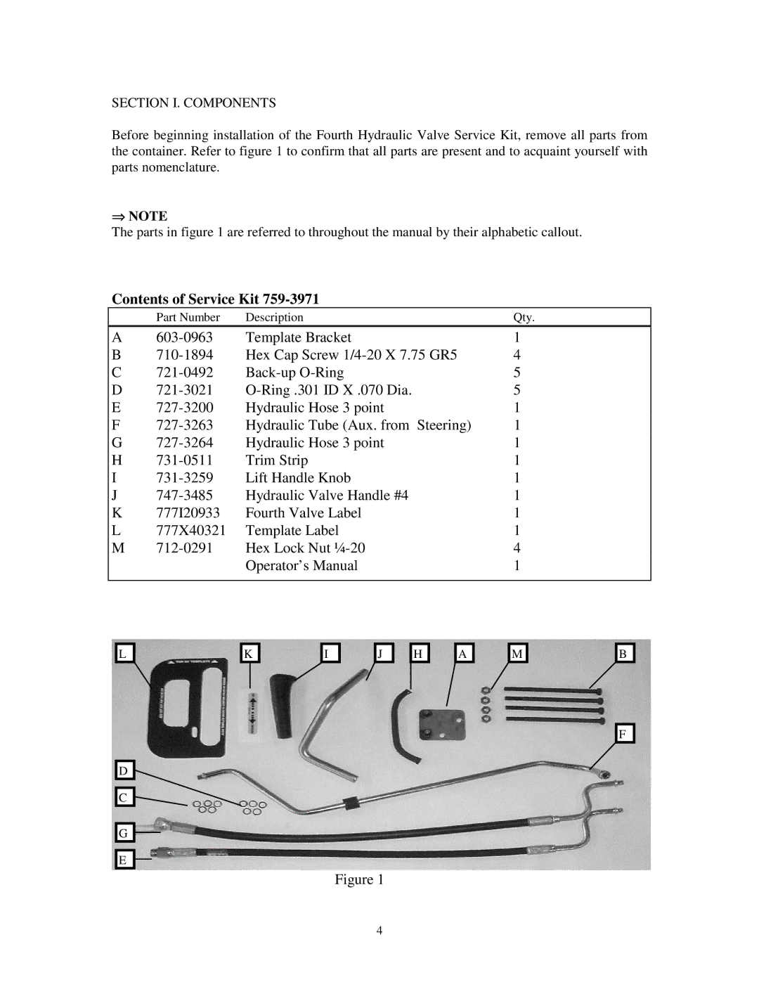
Before beginning installation of the Fourth Hydraulic Valve Service Kit, remove all parts from the container. Refer to figure 1 to confirm that all parts are present and to acquaint yourself with parts nomenclature.
⇒NOTE
The parts in figure 1 are referred to throughout the manual by their alphabetic callout.
Contents of Service Kit 759-3971
| Part Number | Description | Qty. |
|
|
|
|
A | Template Bracket | 1 | |
B | Hex Cap Screw | 4 | |
C | 5 | ||
D | 5 | ||
E | Hydraulic Hose 3 point | 1 | |
F | Hydraulic Tube (Aux. from Steering) | 1 | |
G | Hydraulic Hose 3 point | 1 | |
H | Trim Strip | 1 | |
I | Lift Handle Knob | 1 | |
J | Hydraulic Valve Handle #4 | 1 | |
K | 777I20933 | Fourth Valve Label | 1 |
L | 777X40321 | Template Label | 1 |
M | Hex Lock Nut | 4 | |
|
| Operator’s Manual | 1 |
|
|
|
|
L |
D |
C |
G |
E |
K | I | J | H | A | M |
Figure 1
B |
F |
4
