SECTION II. TRACTOR PREPARATION
Follow the instructions in Section II of the optional Front Hitch System Attachment Owner’s Manual for preparing the tractor for installation.
SECTION III. INSTALLATION
These instructions describe installation of the Fourth Hydraulic Valve Service Kit after the optional Front Hitch System Attachment and optional Hydraulic Angling Attachment OR optional 3 Point Hitch Attachment has been installed on the tractor. As the Fourth Hydraulic Valve Service Kit is being installed along with the Hydraulic Angling Attachment OR 3 Point Hitch Attachment, refer to the installation instructions in the Operator’s Manual that came with all the optional attachments as you complete each of the following steps. Some instructions in one manual may either supersede or supplement instructions in the other.
NOTE: Place a pan beneath the tractor to catch any hydraulic fluid, which may spill during disassembly.
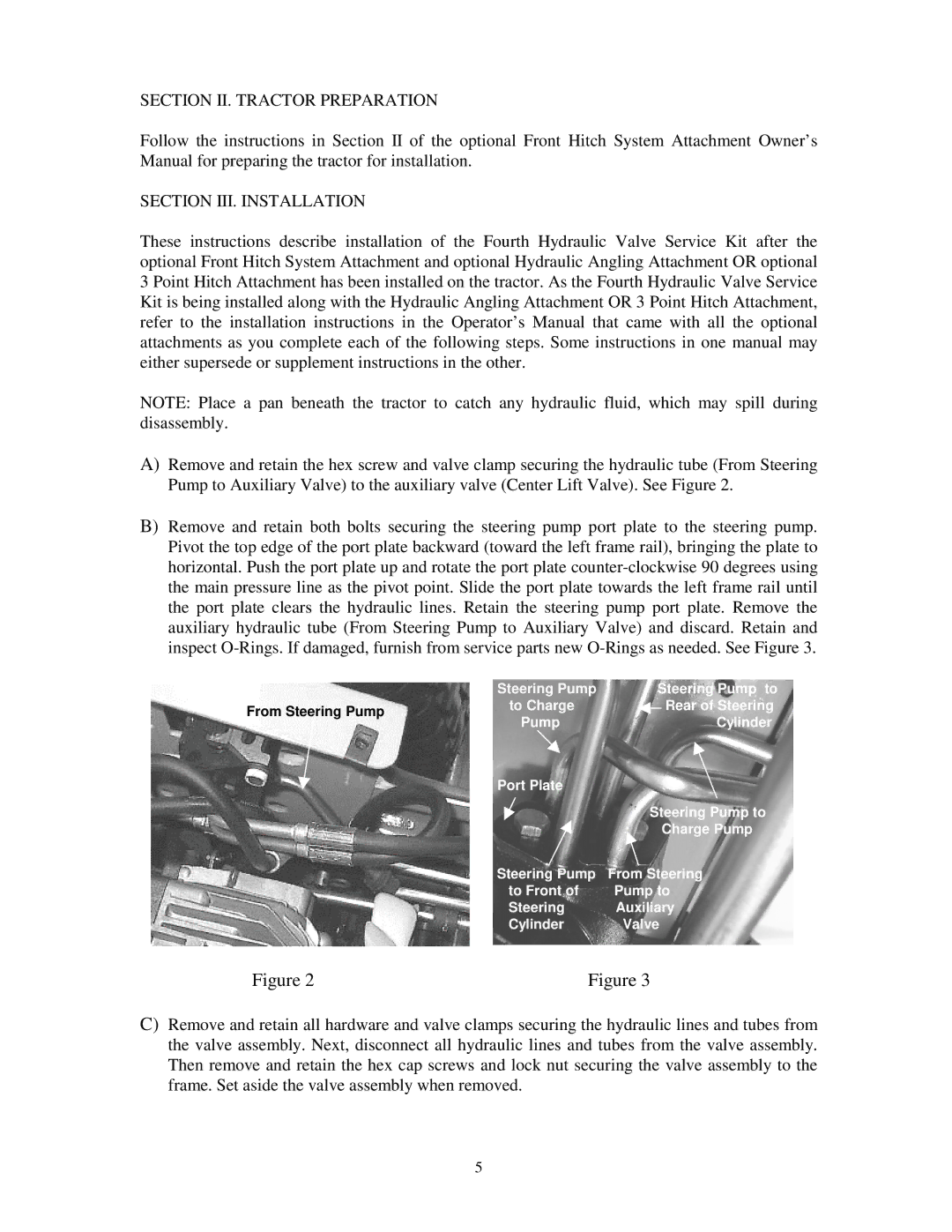
A)Remove and retain the hex screw and valve clamp securing the hydraulic tube (From Steering Pump to Auxiliary Valve) to the auxiliary valve (Center Lift Valve). See Figure 2.
B)Remove and retain both bolts securing the steering pump port plate to the steering pump. Pivot the top edge of the port plate backward (toward the left frame rail), bringing the plate to horizontal. Push the port plate up and rotate the port plate
| Steering Pump | Steering Pump to | |
From Steering Pump | to Charge | Rear of Steering | |
Pump | Cylinder | ||
|
Port Plate
| Steering Pump to |
| Charge Pump |
Steering Pump | From Steering |
to Front of | Pump to |
Steering | Auxiliary |
Cylinder | Valve |
Figure 2 | Figure 3 |
C)Remove and retain all hardware and valve clamps securing the hydraulic lines and tubes from the valve assembly. Next, disconnect all hydraulic lines and tubes from the valve assembly. Then remove and retain the hex cap screws and lock nut securing the valve assembly to the frame. Set aside the valve assembly when removed.
5