16 en Appendix1200 Series IP Video Storage System
34 |
|
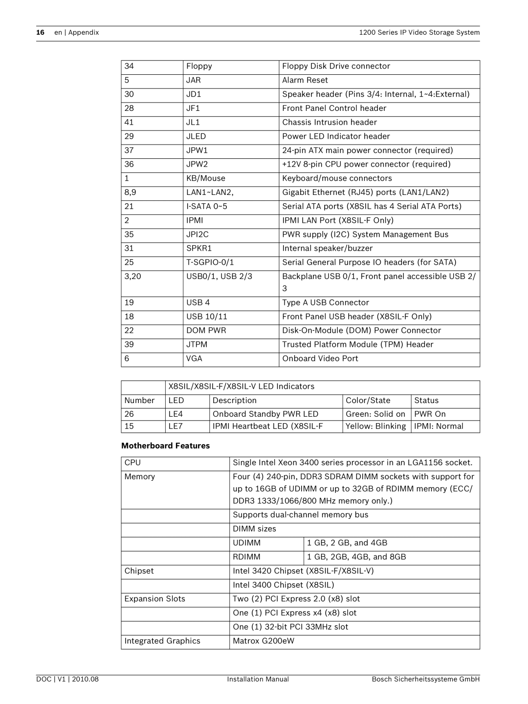
| Floppy | Floppy Disk Drive connector |
| ||
|
|
|
|
|
|
|
|
5 |
|
| JAR | Alarm Reset |
|
| |
|
|
|
|
|
|
|
|
30 |
|
| JD1 | Speaker header (Pins 3/4: Internal, 1~4:External) | |||
|
|
|
|
|
|
|
|
28 |
|
| JF1 | Front Panel Control header |
| ||
|
|
|
|
|
|
|
|
41 |
|
| JL1 | Chassis Intrusion header |
| ||
|
|
|
|
|
|
|
|
29 |
|
| JLED | Power LED Indicator header |
| ||
|
|
|
|
|
|
|
|
37 |
|
| JPW1 | ||||
|
|
|
|
|
|
|
|
36 |
|
| JPW2 | +12V | |||
|
|
|
|
|
|
|
|
1 |
|
| KB/Mouse | Keyboard/mouse connectors |
| ||
|
|
|
|
|
|
|
|
8,9 |
|
| LAN1~LAN2, | Gigabit Ethernet (RJ45) ports (LAN1/LAN2) | |||
|
|
|
|
|
|
|
|
21 |
|
| Serial ATA ports (X8SIL has 4 Serial ATA Ports) | ||||
|
|
|
|
|
|
|
|
2 |
|
| IPMI | IPMI LAN Port |
| ||
|
|
|
|
|
|
|
|
35 |
|
| JPI2C | PWR supply (I2C) System Management Bus | |||
|
|
|
|
|
|
|
|
31 |
|
| SPKR1 | Internal speaker/buzzer |
| ||
|
|
|
|
|
|
|
|
25 |
|
| Serial General Purpose IO headers (for SATA) | ||||
|
|
|
|
|
|
|
|
3,20 |
|
| USB0/1, USB 2/3 | Backplane USB 0/1, Front panel accessible USB 2/ | |||
|
|
|
|
| 3 |
|
|
|
|
|
|
|
|
|
|
19 |
|
| USB 4 | Type A USB Connector |
| ||
|
|
|
|
|
|
|
|
18 |
|
| USB 10/11 | Front Panel USB header | |||
|
|
|
|
|
|
|
|
22 |
|
| DOM PWR | ||||
|
|
|
|
|
|
|
|
39 |
|
| JTPM | Trusted Platform Module (TPM) Header | |||
|
|
|
|
|
|
|
|
6 |
|
| VGA | Onboard Video Port |
| ||
|
|
|
|
|
|
| |
|
|
|
|
| |||
|
|
| |||||
|
|
|
|
|
|
| |
Number | LED |
| Description |
| Color/State | Status | |
|
|
|
|
|
| ||
26 | LE4 |
| Onboard Standby PWR LED | Green: Solid on | PWR On | ||
|
|
|
|
|
| ||
15 | LE7 |
| IPMI Heartbeat LED | Yellow: Blinking | IPMI: Normal | ||
|
|
|
|
|
|
|
|
Motherboard Features
CPU | Single Intel Xeon 3400 series processor in an LGA1156 socket. | |
|
| |
Memory | Four (4) | |
| up to 16GB of UDIMM or up to 32GB of RDIMM memory (ECC/ | |
| DDR3 1333/1066/800 MHz memory only.) | |
|
| |
| Supports | |
|
|
|
| DIMM sizes |
|
|
|
|
| UDIMM | 1 GB, 2 GB, and 4GB |
|
|
|
| RDIMM | 1 GB, 2GB, 4GB, and 8GB |
|
|
|
Chipset | Intel 3420 Chipset | |
|
| |
| Intel 3400 Chipset (X8SIL) | |
|
| |
Expansion Slots | Two (2) PCI Express 2.0 (x8) slot | |
|
| |
| One (1) PCI Express x4 (x8) slot | |
|
| |
| One (1) | |
|
|
|
Integrated Graphics | Matrox G200eW |
|
|
|
|
DOC V1 2010.08 | Installation Manual | Bosch Sicherheitssysteme GmbH |
